
Sun-Power XP Series
Intelligent Gate Controller
INSTALLATION - OWNERS MANUAL
Please do not commence installation
until you have read this instruction booklet
Sun-Power Auto Gates
A division of progressive controls p/l ABN 99-085-262-862
129 Gladstone St Fyshwick ACT 2609
02 64280 4655
Table of Contents
Dear Installer
/
Owner ....................................... 2
Introduction ................................................... 3
Essential Information ......................................... 4
Installation (Standard) ....................................... 5
Side Mount installation .................................... 10
Restricted Side Room installations ....................... 11
Out Swing installation ...................................... 13
Operations ............................................................. 16
Troubleshooting .............................................. 25
DEAR INSTALLER / OWNER
Congratulations on your purchase of the Australian Made
Sun-Power XP Series
Automatic gate operator. The XP operator is a breeze to install. It has been
researched, designed and manufactured to be a
reliable operator with almost non-
existent maintenance required. To save
you time and make installation easier the
XP has a pre-wired control circuit board and placed under the steel weatherproof
cover together with the motor/gears etc. This means that you do not have to spend
time wiring up to a separate control box.
Circuitry for most options is already included. You simply have to connect up the
external devices with no extra boxes or cables required. The design features in the
XP Auto Gate Operator will save you hours on site keeping the installation neat
and tidy. Apart from the physical attributes the control
circuit has some powerful
operating features. These can be adjusted on-site
without modification to suit a
range of situations.
This manual should answer most of your questions regarding the installation
and
operating of the XP Gate operator. If further information is required, please
contact us.
Note the
XP Gate operator
can be purchased as a single gate operator
(Primary) which
comes complete with the Logic Control Circuit Board and can be installed on either
the left- or right-hand side. The dual set includes the above as well as a Secondary
(Slave) operator that does not have the Logic Control.
Introduction
The Sun-Power XP Automatic Gate Operator is an electronically
controlled Automatic
gate operator for swing gates. The
XP
has a range of features that are built in and some
options available and can
be used in a variety of situations.
Solar Power / 240Volt AC
/
12 Volt DC
• Inward or Outward swinging gates
• Restricted side room applications
• Single Gate or pair of Gates
• 90° to 130° opening
A powerful control system gives the flexibility to change some important
characteristics of the operation which include
• Automatic Close / Signal to Close
• Sensitivity to obstacles
•
Multi-User function
The control system
Operates with a wide range of devices
also allows for the
addition of the following:
• Electric locks
• Photoelectric cells (12V DC)
• ‘Palgate’ & ‘Omgate’ for Mobile phone operation
For all its sophistication the
XP
gate operator is extremely reliable
and its robust
construction ensures a long trouble-free life.
Please ensure you read these instructions carefully and any other
instructions supplied then simply follow the step by step instructions.
ESSENTIAL
INFORMATION
PROTECT YOUR WARRANTY Do’s & Don’ts
If you do not understand these instructions, or you have any doubts, it is
most important that you contact us before you apply any power from any
source to the unit or you may void your warranty.
The
XP Gate Operators
are suitable for gates that are correctly hinged and
operate
smoothly and evenly both before and after the XP gate operator is fitted.
The XP gate operator will drive a variety of gate styles sizes and weights.
Keep in mind that a clad gate is ‘A Big Sail’
DO NOT connect to any 240-volt power, solar panel or battery if you do not
understand any of the instructions. DO NOT connect the RED spade terminal
to
the battery until you are ready to set the limit switches.
The RED spade
terminal is supplied disabled from the battery (Not connected to
the battery)
Figure 8 Cable to Slave Motor must be protected in conduit,
Damage to this cable could result in moisture entering, this will prevent the
operator from working correctly
IMPORTANT
All power (240 volt/battery/solar panel) MUST be disconnected before
moving Logic Controller (circuit board) to change battery.
Do not expose any circuit/control board or any electronic circuitry to any
MOISTURE RAIN LUBRICANTS INSECTIDE SPRAY

Installation: Standard Installation
(PULL)
A “Standard installation” is one where the gate(s) open by swinging INWARDS towards
the motor housing. The gate hinge should be no more than 200mm from the rear of the
pier/post. Side room of 350mm is required to accommodate the swing of the arms. If there
is restricted sideroom please refer to that section
Installation Procedure:
1
. Ensure that the gates swing freely and that all existing latches/pad-bolts/chains etc are disabled
or removed from the gate & gate posts
2. When using a 240v unit, the Master operator (the one containing the circuit board) should
be fitted to the gate post nearest the
power supply. Remove the cover(s) from the operator to
access the
slotted fixing holes in the rear of the chassis. Bend the tabs out and
bend them back
against the rear of the chassis, in this position they
act as a spacer allowing the clearance for
the cover(s). NOTE do not remove these tabs – just bend them out and fold them back unless
you are using the OPTIONAL mounting plate.
3. Position each unit on the gate post(s) approximately 50mm from the edge of the
pier/post. The vertical position is found by locating the gate bracket. The gate bracket is best
placed where there is adequate fixing on the gate and the movement of the arms is
unrestricted (See Figure 2). The gate operator may now be bolted
in place.
XP
Gate operator

4. If you have a pair of Gates, connect the SLAVE to the MASTER unit with Fig.8
2 core Flex/Cable Max load 8 Amp at 12 Volts).
Note: This cable is supplied in Dual Gate Kits
DO NOT alter any pre-wiring except Brown & Blue.
Altering pre- wiring (except motor polarity Brown & Blue) will compromise
your
warranty.
The XP operators are set in the factory for a “standard
installation” with the MASTER
placed on the left-hand side (inside
looking out). If the master has to be located on the
right then the motor wires need to be reversed. To accomplish this, locate the
connection blocks for each motor on the Circuit Board. Swap the BROWN and BLUE
wires for Motor 1 and 2
(See figure 3 “Master-Slave connections)
XP
Gate operator

Figure 3 Connections
Cables
1 & 2 Black & Red
From Battery
3 & 4
Black & Red
From Solar Input
or T/Former
If 240/12v
Brown & Blue
Output to Motor 1
Black & Black
Output to Motor 2
[Slave]

Reposition each cam and operate the
XP
again. Repeat until the
gates open and close to
the required positions.
5
. The gate bracket should be positioned so the arms are ALMOST in
a straight line when the
gates are closed (see figure 4). To check the location of the gate brackets first disengage the
Main arm from the drive shaft (using the spanner provided unscrew the bolt until the arm
swings freely) then clamp the gate bracket in position.
Open and close the gate to ensure the
gate bracket is appropriately
located.
6. Connect power (12-volt 24 volt or solar) to the primary operator and connect the battery.
The limit switches may now be adjusted (see figure 5) Each of the
7. Master and Slave operators has its own pair of cams, one to set the open position and one to
set the closed position. Firstly, mark the position of each cam as a reference point before
you loosen the screw holding the cams. Operate the LI-2B operator with the
transmitter and note which cam controls opening and which operates the closing motion
(the cam activates a limit switch to turn off the motor).
XP
Gate Operator
Each XP operator should be fitted to the pier/post with its output
Shaft close to the gate hinge. With this in mind, the standard installation instructions may
now be followed. Special covers are supplied to suit this type of installation.
Restricted Side Room Installations
This term is applied to the situation where the movement of the standard arms cannot be
accommodated within the side room available. In most situations this problem can be
overcome by cutting down the secondary arm (the link joining the gate to the primary arm).
This new length can be approximated by the following procedure:
1. Move the primary arm to a position suitable for the closed gate, , remembering that
in the closed position, the primary and Secondary arms must stop short of a straight-line
alignment (see figure 7)
NOTE
Do not remove these tabs – just bend them out and fold them back to allow space for cover
to slide on to the chassis. There is no need to ben them back if you are using the
OPTIONAL mounting plate.
.
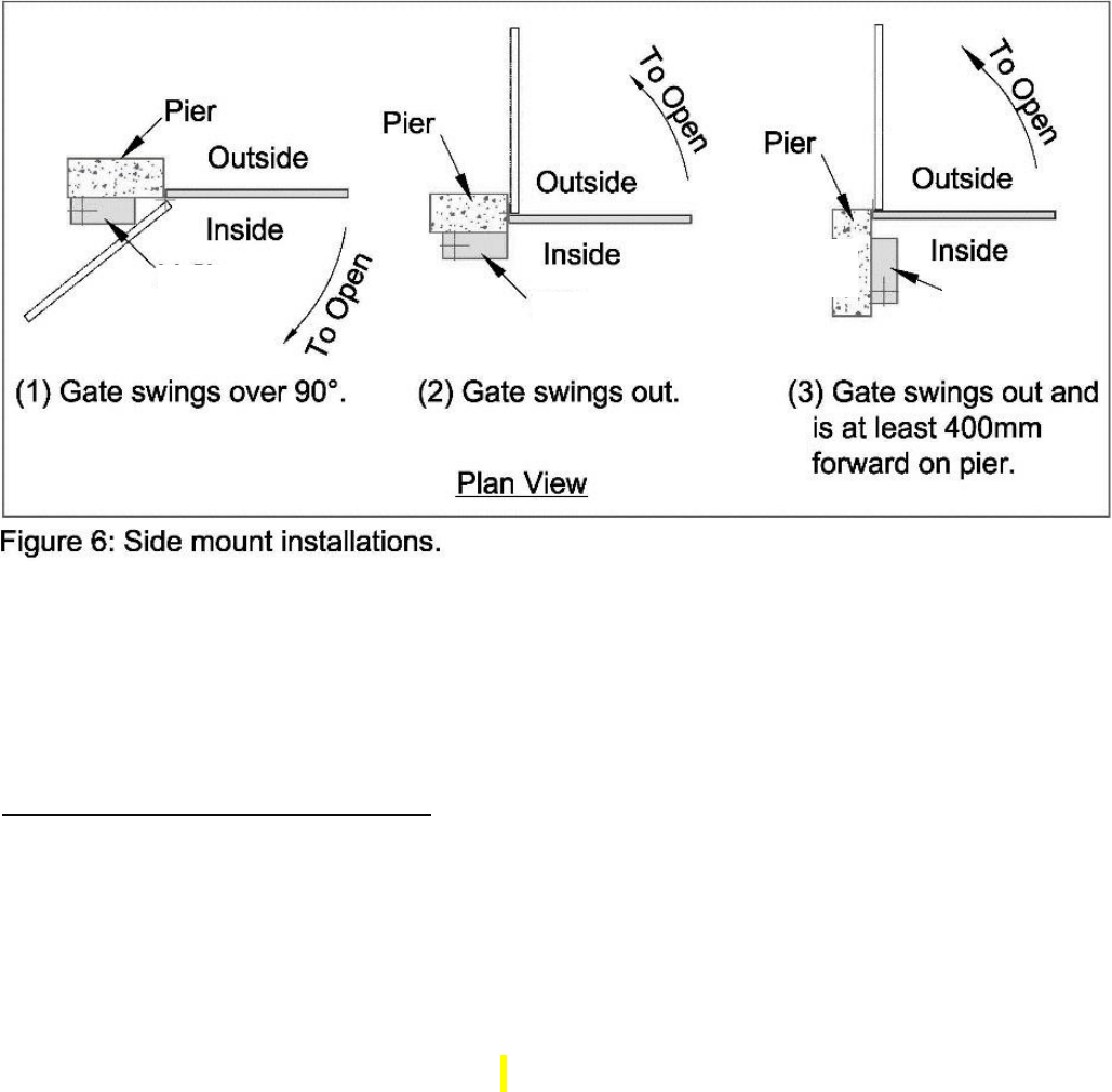
Side Mount Installation
The XP Gate Operator may be mounted sideways, with the long side against the pier/post for
extra flexibility. This feature is very useful for situations where (refer to figure 6)
The gate must swing further than 90 degrees
The gate swings outwards and it is positioned
at least 400mm forward of the back of the pier/post
See also section on out swing installation
5.
XP Gate
Operator
XP Gate
Operator
XP Gate
Operator
XP Gate
Operator

2. Mark a point on the gate suitable for the gate bracket. Holding
the gate bracket in position, measure the distance between the
hole centres on the gate bracket
and primary arm. Move the primary arm to its maximum open position. Open the gate and
measure the distance again (See figure 8). Of the length has changed then the gate bracket
must be re-positioned and the
same process repeated until the dimensions remain the same for
both positions.
Be careful that the secondary arm does not
conflict with the drive shaft of the
primary arm.
Once the dimensions are consistent a new hole can be drilled in the secondary arm and
the arm trimmed to suit. The gate bracket and secondary arm should now be fitted.
XP
Gate Operator
XP
Gate Operator

Out-Swing Installation (PUSH)
In this type of installation, the gate swings outward, away from the XP operator to the
open position.
Several factors must be considered to determine the most suitable arm
length. These include
• The Drive through width required
• The Placement of the Gate Operator
• The location of the Gate on the post/pier
Possible measurements include width between piers/posts, size of piers/posts, single or
double gates, position of hinges on piers/posts etc.
Note: the polarity of the motor connections may need to be reversed for
out-swing installation.
RESET. This button needs to be pushed after changing dip switches
DIP SWITCHES
The dip switches are used to switch between the
modes:
1
OFF
ON
Auto Close
2
OFF
ON
Auto Close with Security
Close
3
MAG
N.C
ELE
N.O
Electronic Lock (on) /
Magnetic Lock
(on)
4
OFF
ON
Pedestrian Auto Close
Electronic Lock NO/NC
Dip switch is used to choose between electronic lock
NO [Normally Open] Magnet Lock or NC [Normally Closed]
Pedestrian Auto Close:
A DIP switch will select whether the leaf will stay open even if the
system is in auto or security close modes. Only Dipswitch [1] & Auto close are ON

TRIMPOTS
Motor 1
– Speed
Potentiometer will set the maximum speed for motor 1
1
Motor 2 – Speed
Potentiometer will set the maximum speed for motor 2
Motor 1 – Max Current
Potentiometer will set the maximum current for motor 1, used to
detect obstruction
Motor 2 – Max Current
Potentiometer will set the maximum current for motor 2, used to
detect obstruction
Flashing Time
Potentiometer will set the time before auto/security close activation
for the flashing light to be activated
Motor 1 – Close
Delay
Potentiometer will set the time delay for motor 1 to close from
activation
Auto Close
Delay
Potentiometer will set the time delay for door to close in auto mode.
This will also act as the timeout in security close mode
Security
Close
Delay
Potentiometer will set the time delay for door to close in security
mode
Courtesy Light
Time
Potentiometer will set he activation time for the courtesy light to
remain on
Security
Delay
Auto
Delay
Courtesy
Time
Motor 1
Delay
Flash
Time
Motor 1
Current
Motor 2
Current
Current
Motor 1
Speed
Motor 2
Speed
MIN
MAX

Standard Operation
On input from either Remote control
/ P
ush button/Mobile Phone/ Keypad one gate
begins to open. The lock output is also activated for 3 seconds. If you have a pair of Gates
then after 2 seconds the second gate begins to open.
Gates will fully open unless they meet an obstruction in which case the gate(s) will s
top and
wait for further signal. If closing Gate(s) meet an obstruction they will reverse to the open
position.
Auto
Close Mode
Gates will automatically close after selected delay
time has been reached
Security Close Mode (Multi User]
]]Function)
This function is for when the
XP
Gate operator is installed for multi-users
(eg flats,
apartments etc). In this mode the gate operator will ignore close signals
and continue to open
(auto-close/security close mode only).
Pedestrian mode
Select this mode for limited Pedestrian opening
Settings
Overloads
– the overloads are pre-set to maximum sensitivity (eg slight pressure will
cause the
operator to STOP if it is opening or STOP & OPEN if it is closing. Note if
these functions are reversed
(the gate STOPS when closing and STOPS and REVERSES
when opening then the polarity of the motor
connections MUST BE REVERSED and the
limit switch cams adjusted.
There is ONE overload for each gate as indicated on the main circuit board (Refer Figure 9). To
reduce the sensitivity on the main circuit board, turn the overload dials
in the
anti-clockwise
direction.
BE CAREFUL
large reductions in sensitivity may allow
the gate(s) to exert excessive
pressure on people or vehicles trapped in the path of the gate(s).
Motor 1 Delay
– Turning the dials/trimpots anti-clockwise gives the minimum delay.
Turning the dials/trimpots clockwise will give the maximum delay.
Auto Close
– the operator control board is supplied with a dip-switch installed on the
Board. This allows the gate to automatically close after a specific period. This period
is
adjustable (refer figure 9).
• Turn “auto delay” dial (trimpot) clockwise to increase the hold open
time delay before gate closes automatically
• Turn/dial trimpot anti-clockwise to shorten the hold open time delay
before gate closes automatically

Auto
Close
Dip Switch 1 ON
Auto Close
Delay
SOLAR
OR DC IN
MAX 20w
GND +
BATTERY
GND +
MOTOR
1
MOTOR
2
COURTESY
LIGHT
GND +
FLASH
GND +
AUX
GND +
LOCK
- LATCH
GND +

Photo-electric safety cell [Optional] [12-volt operators only)
– An appropriate photo electric safety
cell
(PE)
may be fitted to detect obstructions in the path of the gate(s). The
PE
will check for
obstructions during the closing cycle only. If an obstruction is encountered the gate(s) will
reverse to the open position. If the gate is set in the automatic close mode the gate(s) will
remain open until the obstruction is cleared.
Wires from the
PE
should be attached to the appropriate connection block (see figure 9)
Note: extra power consumption will occur when using Photoelectric Cells so extra size
Panel and battery will be required when gate(s) are operating on solar power only.
Push-button
/
Key-Pad etc – Wireless Keypads & Hardwired Keypads are available
from Sun-Power to
operate the
XP operator
. Input should be in the form of a MOMENTARY
CLOSED CIRCUIT.
WARNING! Voltage must not be applied to these terminals. Damage to
the circuitry will
result if voltage is applied. Devices that send a Voltage Pulse (as some intercoms do)
must be connected to the circuit board through a relay.
P
INPUT CABLES WIRE BRIDGE
FOR WIRED WHEN NO SAFETY PE BEAM
PUSH BUTTON

Electric Lock / Mag Lock
- Connection for an electric lock/latch (EL) are provided on the circuit
board. (see figure 9). This connection block will supply 12 Volts to energise
the lock at the
beginning of the opening and closing cycles.
OUTPUT to LATCH - LOCK

Solar Wiring
Detail
DO NOT
connect solar panel until all other settings and adjustments have
been
completed.
For optimum charging clean solar panels regularly.
Step 1. Locate the two-way terminal connection block on top plate near motor.
This will have Red (positive) and Black (negative) wires. Connect solar panel direct to it.
Connect
SOLAR PANEL
Red to Red
Black to Black
IMPORTANT
As a connected solar panel delivers a charge, the solar panel must be covered or Disconnected
when any work or wiring is being done on the control board (other
than when adjusting
trimpots or limit switches)
Step 2
Locate
RED
wire with spade terminal (which will be disabled from Positive on
Battery).
Connect this wire and you are ready to set your limits.
Negative
BLACK
wire is already connected
Locate Positive Wire (RED)
Connect
RED
wire to
+
on battery
Note:
XP gate operator kits (solar, 240 volt and 12 volt) are supplied complete with a 9 Amp hour
battery. This battery should be checked regularly.

TROUBLESHOOTING
Poor range with the radio transmitter (Tx).
Tx10 Standard transmitters are factory tested to 200 metres.
Range will vary at different locations
Gate Operator Kit includes a 433Mhz Antenna +
Radio Receiver (Rx).
Poor range may occur for several reasons. The first two things
to check are:
• The Battery in the Tx [Transmitter/Remote Control]
• Antenna installation and wiring
Note: Livestock have a habit of chewing cables add protection as necessary
Other causes may be interference from other Radio Sources such as
•
Electric fences
• Baby monitors
• Other local transmitters
Here the best solution is to remove the external source. If this is not possible the problem
may sometimes be solved by using special frequency transmitters and a
matching Radio
receiver (Rx).
These are options that must specifically be ordered.
Other faults may be due to incorrect settings. Refer to the “settings” section of this
manual to ensure the settings are correct.
PA
SOME OPTIONS
RX500 Standalone Radio
Receiver. Ideal for fitting
to most Roller & Panel
lift doors to allow use of
Tx10 Remote Control on
BOTH Gate & Garage
Door $105.00 each
Note: Input power supply
must be 12/24v DC
PALGATE
‘Bluetooth’
SG B10 LITE
ACCESS CONTROL
PALGATE SG-30-3GA-WR
Remote Mobile
Phone Access
SIM Card required
-----------------------------
PALGATE
SG-30-4GA-WR-
T21Combination
Mobile & Remote
Control Access Remotes
SIM Card fees will apply
Ext. Range
antenna available

.
Programming Transmitters
Important: The Radio receiver, Remote Controls and Digital KeyPad are generally
pre-programmed. Instructions below are for re-programming if necessary.
Remote Control
(TX10)
Keypad batteries are fitted
with an isolation strip – please
remove this strip before
using.
1) Enter pin code in to keypad
(factory default = 1234).
2) Press & release ‘LEARN’
button (red light will turn on)
3) Press & hold # Key on
keypad until gate motor
responds.
N.B. Sequence needs to be
fairly quick.
TO CHANGE KEYPAD’s PIN CODE:
Use existing code
(e.g. 1234 by factory default).
1) Punch in the current code.
2) Then press the * key.
3) Enter the new code.
4) Press the * key again.
5) Enter the new code again.
6) Press the # key.
When buzzer sounds for
1 second, the change is
complete.
Sequence example:
1234*8552*8552#
DK50 Wireless Keypad
For domestic use ONLY
1. Press & immediately
release the ‘LEARN’ button
On Radio receiver module
(red light will turn on)
2) Now Immediately Press
preferred button on remote
(e.g. ‘A’ or ‘1’) and hold for 2
Seconds or until gate begins
to drive.
N.B. Sequence needs to be
fairly quick.
Design & colour of remote
controls may alter.
SPXPPB-RAD-2
Wireless Push
button
with 2 position key
switch.
Button active -
Button inactive
Push Buttons
program the same
way as Remote
Controls

Programming your Transmitters:
Troubleshooting Remotes and Keypads/ FAQ
I tried changing the pin code on my
wireless DK50 keypad. Now I can’t
remember the new code!
Easily remedied! To reset back to factory
default (1234), disconnect the keypad’s
battery for 15 seconds.
Press and hold the * and # keys together.
Keeping them held, reconnect the battery.
A 1-second buzzer will sound to confirm
the reset. If you get a
3-second beep, you’re doing it wrong.
I tried to program a new remote control
and/or keypad to the receiver and now
NONE of my remote controls work!
Another mistake that is easily remedied!
When you tried to program your new
transmitter, you possibly held the Learn
button down for too long. If held for 6 –
8 seconds (or longer), the receiver will
delete all previously programmed
transmitters (remotes & keypads etc).
This is a security feature that is useful
when an employee leaves but takes their
access remote with them. In deleting all
codes, you have accidentally accessed a
function normally reserved for
technicians only. Simply re-program your
remotes and this time only press the
programming button until RED light
comes on. The Learn sequence needs to
be done quickly.
Sounds like a flat battery in your
remote! Time for a new one. Your
local hardware store should have the
right battery to suit your remote.
I press the button on my remote and
the little light on it isn’t coming on.
My gate won’t open either!
I press the buttons on my keypad but
it’s not making any beeps like it used
to. What do I do?!
Sounds like a flat battery! Time for a
new one! Your local hardware store
should be able to provide you with
replacement batteries.
There’s a green LED lighting up on my
keypad. Normally it’s red. What
does that mean?
That’s the early-warning light to let
you know that your battery is almost
completely flat.
We had someone do some work on
our fence last week and now my
remote control and keypad do not
work.
Electric fences can interfere with
communication between your
transmitters and the receiver module
inside your motor. Have you got your
aerial connected to your receiver? Is
it mounted properly?

Details & Freight Dimensions Sun-Power XP Series Auto Gate Operators
Chassis & Case 245mm High x 140mm Wide x 335mm Deep
Primary arm. Pivot centres 540 mm Secondary arm. Pivot centres 545mm
Sizes & Weights of various Kits:
XP 100 Single 240v Kit
1 Ctn. 360mm x 325mm x 150mm + 1 Bundle 700 x 75 x 75mm 21 Kg
XP 100/300 Double 240v Kit
2 Ctns. 360mm x 325mm x 150mm + 1 Bundle 700 x 75 x 75mm 38 Kg
XP 200 Single Solar Kit
1 Ctn. 360mm x 325mm x 150mm + 1 Ctn 610 x 415 x 170mm 25 Kg
XP 200/300 Solar Double Kit
2 Ctns. 360mm x 325mm x 150mm + 1 Ctn 610 x 415 x 170mm 40 Kg
XP 300 Slave Operator with Arm assembly & gate bracket
1 Ctn. 360mm x 325mm x 150mm
+ 1 Bundle [Arm] 700 x 75 x 75mm 22Kg
Warranty
Sun-Power XP Series Auto Gate Operators are warranted as follows…
Electronics: 1 Year Mechanical: 2 Years
All warranties implied or otherwise are “Back to Base”
ie;
Products under claim to be returned for warranty assessment/and or
repair at buyer’s expense. Sun-Power [SP] warrants to replace or repair
individual components at their discretion, this may require client shipping
component[s] [for Sun-Power to assess], at client’s cost.
Record of Purchase: Date: ______/_____/________
Purchased From: ___________________________________ Inv. No. _____________
Product Purchased: ___________________________________________________
Serial No. _______________________
Notes: ________________________________________________________________
_________________________________________________________________
_

[Type here]
23
