
8.914-366.0-R 07/26/16
Hotsy 1200
Operator’s Manual
Pressure Washer
MODELS: 1260SS
1.110-533.0
1270SS
1.110-557.0
1280SS
1.110-558.0
1260SSG
1.110-535.0
1270SSG
1.110-536.0
1280SSG
1.110-537.0
1285SS
1.110-043.0
1290SS
1.110-538.0
1285SSG
1.110-044.0
1290SSG
1.110-539.0
For the Hotsy Dealer nearest you,
consult our web page at
www.hotsy.com

2 Hotsy 1200 8.914-366.0 - R
Machine Data Label

3
Table of Contents
Machine Data Label. . . . . . . . . . . . . . . . . . . . . . . . . .2
Table of Contents . . . . . . . . . . . . . . . . . . . . . . . . . . .3
How To Use This Manual . . . . . . . . . . . . . . . . . . . . .4
Safety
Introduction & Safety Information . . . . . . . . . . . . . . .5
INPORTANT SAFETY INFORMATION . . . . . . . . . .6
Operations
Technical Specification . . . . . . . . . . . . . . . . . . . . . . .9
Component Identification . . . . . . . . . . . . . . . . . . . .10
Assembly Instructions. . . . . . . . . . . . . . . . . . . . . . .11
Installation. . . . . . . . . . . . . . . . . . . . . . . . . . . . . . . .12
Operation Instructions. . . . . . . . . . . . . . . . . . . . . . .14
Detergents & General Washing Techniques. . . . . .16
Shutdown Instructions. . . . . . . . . . . . . . . . . . . . . . .17
Storage . . . . . . . . . . . . . . . . . . . . . . . . . . . . . . . . . .17
Maintenance
Pump. . . . . . . . . . . . . . . . . . . . . . . . . . . . . . . . . . . .18
Burner Fuel Filter . . . . . . . . . . . . . . . . . . . . . . . . . .18
Heating Coil . . . . . . . . . . . . . . . . . . . . . . . . . . . . . .18
Engine. . . . . . . . . . . . . . . . . . . . . . . . . . . . . . . . . . .18
Oil Burner Blower Motor . . . . . . . . . . . . . . . . . . . . .18
Battery. . . . . . . . . . . . . . . . . . . . . . . . . . . . . . . . . . .18
Troubleshooting . . . . . . . . . . . . . . . . . . . . . . . . . . .19
Parts
Coil & Chassis - 1260SSG, 1270SSG, 1280SSG,
1285SSG 1290SSG. . . . . . . . . . . . . . . . . . . . 24
Power Platform - 1260SSG, 1270SSG, 1280SSG,
1285SSG 1290SSG. . . . . . . . . . . . . . . . . . . . 25
Parts - 1260SSG, 1270SSG, 1280SSG, 1285SSG
1290SSG . . . . . . . . . . . . . . . . . . . . . . . . . . . . 26
Coil & Chassis - 1260SS, 1270SS, 1280SS, 1285SS,
1290SS . . . . . . . . . . . . . . . . . . . . . . . . . . . . . 30
Power Platform - 1260SS, 1270SS, 1280SS, 1285SS,
1290SS . . . . . . . . . . . . . . . . . . . . . . . . . . . . . 31
Parts - 1260SS, 1270SS, 1280SS, 1285SS, 1290SS
32
Engine Gasoline Tank. . . . . . . . . . . . . . . . . . . . . . 36
Control Box . . . . . . . . . . . . . . . . . . . . . . . . . . . . . . 38
Float Tank. . . . . . . . . . . . . . . . . . . . . . . . . . . . . . . 40
Burner Fuel Oil Tank. . . . . . . . . . . . . . . . . . . . . . . 42
Coil Outlet . . . . . . . . . . . . . . . . . . . . . . . . . . . . . . . 43
Burner . . . . . . . . . . . . . . . . . . . . . . . . . . . . . . . . . . 44
Specifications . . . . . . . . . . . . . . . . . . . . . . . . . . . . 46
Pump - 1260SSG . . . . . . . . . . . . . . . . . . . . . . . . . 48
Pump - 1270SSG, 1280SSG, 1285SSG, 1290SSG. .
50
Pump Super Duty "Option" - 1285SSG. . . . . . . . . 52
Hose, Gun, & Wand . . . . . . . . . . . . . . . . . . . . . . . 54
HX. 2 Pump Series . . . . . . . . . . . . . . . . . . . . . . . . 55
HM.3 Series Pump . . . . . . . . . . . . . . . . . . . . . . . . 58
VRT3 Unloader . . . . . . . . . . . . . . . . . . . . . . . . . . . 60
Crossfire Burner . . . . . . . . . . . . . . . . . . . . . . . . . . 62
Wiring Diagram - 1260SS, 1280SS . . . . . . . . . . . 65
Wiring Diagram - 1270SS, 1280SS, 1290SS . . . . 66
Wiring Diagram - 1260SSG, 1285SSG. . . . . . . . . 67
Wiring Diagram - 1270SSG, 1280SSG, 1290SSG 68
Wire Routing Diagram. . . . . . . . . . . . . . . . . . . . . . 69
Hotsy 1200 8.914-366.0 - R

4
How To Use This Manual
This manual contains the following sections:
• How to Use This Manual
•Safety
• Operations
• Maintenance
• Parts List
The HOW TO USE THIS MANUAL section will tell you
how to find important information for ordering correct
repair parts.
Parts may be ordered from authorized dealers. When
placing an order for parts, the machine model and
machine serial number are important. Refer to the
MACHINE DATA box which is filled out during the
installation of your machine. The MACHINE DATA box
is located on the inside of the front cover of this manual.
The model and serial number of your machine is
located on the back of the machine.
The SAFETY section contains important information
regarding hazardous or unsafe practices of the
machine. Levels of hazards are identified that could
result in product damage, personal injury, or severe
injury resulting in death.
The OPERATIONS section is to familiarize the operator
with the operation and function of the machine.
The MAINTENANCE section contains preventive main-
tenance to keep the machine and its components in
good working condition. They are listed in this general
order:
•Pump
• Burner Fuel Filter
•Heating Coil
•Engine
• Oil Burner Blower Motor
• Battery
• Troubleshooting
The PARTS LIST section contains assembled parts
illustrations and corresponding parts list. The parts lists
include a number of columns of information:
• REF – column refers to the reference number
on the parts illustration.
• PART NO. – column lists the part number for
the part.
• QTY – column lists the quantity of the part used
in that area of the machine.
• DESCRIPTION – column is a brief description
of the part.
• NOTES – column for information not noted by
the other columns.
NOTE: If a service or option kit is installed on your
machine, be sure to keep the KIT INSTRUCTIONS
which came with the kit. It contains replacement parts
numbers needed for ordering future parts.
NOTE: The manual part number is located on the
lower right corner of the front cover.
Model:
Date of Purchase:
Serial Number:
Dealer:
Address:
Phone Number:
Sales Representative:
Hotsy 1200 8.914-366.0 - R

5
Safety
Introduction & Safety Information
Thank you for purchasing this Pressure Washer. We
reserve the right to make changes at any time
without incurring any obligation.
Owner/User Responsibility:
The owner and/or user must have an understanding of
the manufacturer’s operating instructions and warnings
before using this pressure washer. Warning information
should be emphasized and understood. If the operator
is not fluent in English, the manufacturer’s instructions
and warnings shall be read to and discussed with the
operator in the operator’s native language by the
purchaser/owner, making sure that the operator
comprehends its contents.
Owner and/or user must study and maintain for future
reference the manufacturers’ instructions.
The operator must know how to stop the machine
quickly and understand the operation of all controls.
Never permit anyone to operate the engine without
proper instructions.
SAVE THESE INSTRUCTIONS
This manual should be considered a permanent part of
the machine and should remain with it if machine is
resold.
When ordering parts, please specify model and
serial number. Use only identical replacement parts.
This machine is to be used only by trained opera-
tors.
Danger: This pressure washer is classified for
“Outdoor Use Only - Store Indoors”. Running this
product indoors can result in death due to carbon
monoxide, a poisonous gas you cannot see or
smell. Never operate indoors, even if windows and
doors are open. Only use outdoor and far away
from windows, doors, and openings or vents.
Hotsy 1200 8.914-366.0 - R

6
Safety
INPORTANT SAFETY INFORMATION
WARNING: If you do not follow these instructions
exactly, a fire or explosion may result, causing
property damage, personal injury or loss of life.
WARNING: To reduce the risk of
injury, read operating instructions
carefully before using.
1.
Read owner's manual thoroughly.
Failure to follow instructions
could cause malfunction of the
machine and result in death,
serious bodily injury and/or
property damage.
2. Know how to stop the machine and bleed pressure
quickly. Be thoroughly familiar with the controls.
3. Stay alert — watch what you are doing.
DANGER: Keep wand, hose, and
water spray away from electric
wiring or fatal electric shock may
result.
4. All installations must comply
with local codes. Contact your
electrician, plumber, utility
company or the selling dealer
for specific details.
WARNING: This machine exceeds
85 db appropriate ear protection
must be worn.
WARNING: High pressure spray
can cause paint chips or other
particles to become airborne and
fly at high speeds. To avoid
personal injury, eye, hand and
foot safety devices must be worn.
5. Always were properly rated eye
protection such as safety
goggles or face shield while
spraying.
(Safety glasses do not provide full protection)
6. Keep operating area clear of all persons.
WARNING: Flammable liquids can
create fumes which can ignite,
causing property damage or
severe injury.
WARNING: Risk of explosion —Do
not Spray flammable liquids.
Operate only where open flame or
torch is permitted.
WARNING: Risk of fire — Do not
add fuel when the product is
operating or still hot.
WARNING: Do not use gasoline
crankcase draining or oil
containing gasoline, solvents or
alcohol. Doing so will result in fire
and/or explosion.
7. Allow engine to cool for 1-2 minutes before refu-
eling. If any fuel is spilled, make sure the area is
dry before testing the spark plug or starting the
engine. (Fire and/or explosion may occur if this is
not done.)
Gasoline engines on mobile or portable
equipment shall be refueled:
a. outdoors;
b. with the engine on the equipment stopped;
c. with no source of ignition within 10 feet of
the dispensing point; and
d. with an allowance made for expansion of the
fuel should the equipment be exposed to a
higher ambient temperature.In an overfilling sit-
uation, additional precautions are necessary to
ensure that the situation is handled in a safe
manner.
WARNING: Risk of injury. Disconnect battery
ground terminal before servicing.
8. When in use, do not place machine near
flammable objects as the engine is hot.
9. Oil burning appliances shall be installed only in
locations where combustible dusts and flammable
gases or vapors are not present. Do not store or
use gasoline near this machine.
10. Use No. 1 or No. 2 heating oil (ASTM D306) only.
NEVER use gasoline in your fuel oil tank. Gasoline
is more combustible than fuel oil and could result in
a serious explosion. NEVER use crankcase or
waste oil in your burner. Fuel unit malfunction could
result from contamination.
Hotsy 1200 8.914-366.0 - R
WARNING
READ OPERATOR’S
MANUAL THOROUGHLY
PRIOR TO USE.
OPERATIONS
SAFETY
MAINTENANCE
DANGER
KEEP WATER
SPRAY AWAY FROM
ELECTRICAL WIRING.
WARNING
EAR PROTECTION
MUST BE WORN
WARNING
RISK OF EXPLOSION:
OPERATE ONLY WHERE
OPEN FLAME OR TORCH
IS PERMITTED
WARNING
USE PROTECTIVE
EYE WEAR
AND CLOTHING
WHEN OPERATING
THIS EQUIPMENT.
WARNING
RISK OF FIRE.
DO NOT ADD FUEL
WHEN OPERATING
MACHINE.

7
Safety
11. Do not confuse gasoline and fuel oil tanks. Keep
proper fuel in proper tank.
WARNING: Risk of injury. Hot
surfaces can cause burns. Use
only designated gripping areas of
spray gun and wand. Do not
place hands or feet on non-
insulated areas of the pressure
washer.
12. Transport/Repair with fuel tank EMPTY or with fuel
shut-off valve OFF.
WARNING: Hot discharge fluid. Do not touch or
direct discharge stream at persons.
WARNING: This machine
produces hot water and must
have insulated components
attached to protect the operator.
13. To reduce the risk of injury, close
supervision is necessary when a
machine is used near children.
Do not allow children to operate
the pressure washer. This machine must be
attended during operation.
WARNING: Grip cleaning wand
securely with both hands before
starting. Failure to do this could
result in injury from a whipping
wand.
14. Never make adjustments on
machine while in operation.
15. Be certain all quick coupler fittings are secured
before using pressure washer.
WARNING: High pressure developed
by these machines will cause
personal injury or equipment
damage. Keep clear of nozzle. Use
caution when operating. Do not
direct discharge stream at people
and animals, or severe injury or
death will result.
WARNING: Protect machine from
freezing.
16. To keep machine in best
operating conditions, it is
important you protect machine
from freezing. Failure to protect
machine from freezing could
cause malfunction of the
machine and result in death,
serious bodily injury, and/or property damage.
Follow storage instructions specified in this
manual.
17. Inlet water must be clean fresh water and no hotter
then 90°F.
WARNING: Risk of asphyxiation.
Use this product only in a well
ventilated area.
18. Avoid installing machines in
small areas or near exhaust
fans. Adequate oxygen is
needed for combustion or
dangerous carbon monoxide
will result.
19. Manufacturer will not be liable for any changes
made to our standard machines or any compo-
nents not purchased from us.
20. The best insurance against an accident is precau-
tion and knowledge of the machine.
WARNING: Be extremely careful
when using a ladder, scaffolding
or any other relatively unstable
location. The cleaning area
should have adequate slopes and
drainage to reduce the possibility
of a fall due to slippery surfaces.
Hotsy 1200 8.914-366.0 - R
WARNING
RISK OF INJURY.
HOT SURFACES
CAN CAUSE BURNS
WARNING
HOT DISCHARGE FLUID:
DO NOT TOUCH OR
DIRECT DISCHARGE
STEAM AT PERSONS.
WARNING
TRIGGER GUN KICKS
BACK — HOLD WITH
BOTH HANDS
WARNING
RISK OF INJECTION
OR SEVERE INJURY
TO PERSONS. KEEP
CLEAR OF NOZZLE.
WARNING
PROCTECT FROM
FREEZING
WARNING
RISK OF
ASPHYXIATION.
USE THIS PRODUCT
ONLY IN A WELL
VENTILATED AREA.
WARNING
RISK OF INJURY
FROM FALLS WHEN
USING LADDER.

8
Safety
21. Do not allow acids, caustic or abrasive fluids to
pass through the pump.
22. Never run pump dry or leave spray gun closed
longer than 1-2 minutes.
23. Machines with shut-off spray gun should not be
operated with the spray gun in the off position for
extensive periods of time as this may cause
damage to the pump.
24. Protect discharge hose from vehicle traffic and
sharp objects. Inspect condition of high pressure
hose before using or bodily injury may result.
25. Before disconnecting discharge hose from water
outlet, turn burner off and open spray gun to allow
water to cool below 100° before stopping the
machine. Then open the spray gun to relieve
pressure. Failure to properly cool down or maintain
the heating coil may result in a steam explosion.
26. Do not overreach or stand on unstable support.
Keep good footing and balance at all times.
27. Do not operate this machine when fatigued or
under the influence of alcohol, prescription medica-
tions, or drugs.
28. In oil burning models, use only kerosene, No. 1
home heating fuel, or diesel. If diesel is used, add a
soot remover to every tankful.
WARNING: If connection is made
to portable water supply, a back
flow device must be provided.
Follow the maintenance instructions
specified in the manual.
WARNING
DO NOT SPRAY
MACHINE OR ANY
PEOPLE, ANIMALS OR
ELECTRICAL PARTS.
Hotsy 1200 8.914-366.0 - R
WARNING
NOT SUITABLE
FOR CONNECTION
TO THE POTABLE
WATER MAINS.

9
Operations
Technical Specification
Model #
Pump Volume @
Pump Head
Pump Pressure at
Pump Head
Burner Type
Burner Fuel
Pressure
1260SS 4.3 GPM / 258 GPH 3000 PSI
Fuel Oiled Fired, 385,000
BTU/Hr.
NOT TO EXCEED
200 PSI
1270SS 4.5 GPM / 270 GPH 4000 PSI
Fuel Oiled Fired, 385,000
BTU/Hr.
NOT TO EXCEED
200 PSI
1280SS 5.2 GPM / 306 GPH 3500 PSI
Fuel Oiled Fired, 385,000
BTU/Hr.
NOT TO EXCEED
200 PSI
1260SSG 4.3 GPM / 258 GPH 3000 PSI
Fuel Oiled Fired, 398,000
BTU/Hr.
NOT TO EXCEED
200 PSI
1270SSG 4.5 GPM / 270 GPH 4000 PSI
Fuel Oiled Fired, 398,000
BTU/Hr.
NOT TO EXCEED
200 PSI
1280SSG 5.2 GPM / 306 GPH 3500 PSI
Fuel Oiled Fired, 398,000
BTU/Hr.
NOT TO EXCEED
200 PSI
1285SS 5.2 GPM / 306 GPH 3500 PSI
Fuel Oiled Fired, 385,000
BTU/Hr.
NOT TO EXCEED
200 PSI
1290SS 5.6 GPM / 336 GPH 3000 PSI
Fuel Oiled Fired, 385,000
BTU/Hr.
NOT TO EXCEED
200 PSI
1285SSG 5.2 GPM / 306 GPH 3500 PSI
Fuel Oiled Fired, 398,000
BTU/Hr.
NOT TO EXCEED
200 PSI
1290SS 5.6 GPM / 336 GPH 3000 PSI
Fuel Oiled Fired, 398,000
BTU/Hr.
NOT TO EXCEED
200 PSI
Model #
Burner Exhaust
Stack
Machine
Power
Machine
Weight
Shipping
Weight
Machine Dimensions
1260SS 10”
Briggs
Vanguard
690 Lbs 780 Lbs L 45” X W 33” X H 52”
1270SS 10”
Honda
GX630
750 Lbs 840 Lbs L 45” X W 33” X H 52”
1280SS 10”
Honda
GX630
750 Lbs 840 Lbs L 45” X W 33” X H 52”
1260SSG 10”
Briggs
Vanguard
720 Lbs 810 Lbs L 45” X W 33” X H 52”
1270SSG 10”
Honda
GX630
780 Lbs 870 Lbs L 45” X W 33” X H 52”
1280SSG 10”
Honda
GX630
780 Lbs 870 Lbs L 45” X W 33” X H 52”
1285SS 10”
Briggs
Vanguard
750 Lbs 840 Lbs L 45” X W 33” X H 52”
1290SS 10”
Honda
GX630
750 Lbs 840 Lbs L 45” X W 33” X H 52”
1285SSG 10”
Briggs
Vanguard
780 Lbs 870 Lbs L 45” X W 33” X H 52”
1290SS 10”
Honda
GX630
780 Lbs 870 Lbs L 45” X W 33” X H 52”
Hotsy 1200 8.914-366.0 - R

10
Operations
Component Identification
Pump — Delivers a specific gpm to the high pressure
nozzle which develops pressure.
Spray Gun — Controls the application of water and
detergent onto cleaning surface with trigger device.
Includes safety latch.
Detergent Valve — Allows you to siphon and mix
detergents
Wand — Must be connected to the spray gun.
High Pressure Hose — Connect one end to water
pump high pressure discharge nipple and the other end
to spray gun.
Unloader Valve — Safety device which, when the
spray gun closes, prevents over pressurization.
Bend Restrictor (Shroud) — This shroud has different
lengths depending on pressure. The largest shroud
must be connected to the spray gun to protect operator
if hose becomes separated.
Hotsy 1200 8.914-366.0 - R
Burner
Exhaust
Batte
ry
Box
Relief
Valve
Engine
Pump
Unloader
Valve
Control Box
Float
Tank
Water
Inlet
Detergent
Valve
Fuel Oil
Tank
Gasoline
Tank
High
Pressure
Hose
Spray
Gun
Generator
120V “G”
Models On
ly
Detergent Line
w/Screen
Pressure
Nozzle
Spray Wand
Shroud

11
Operations
Assembly Instructions
Unpacking
Unpack carefully. Wear safety glasses or goggles while
unpacking, assembling, or operating pressure washer.
If there are missing components or hidden damage,
immediately contact carrier concerning discrepancies.
Parts Included
• Pressure Washer
• Pressure Hose
• Pressure Nozzles (3 Ea.)
•Wand
• Trigger Gun
• Operations Manual
• Gasoline Engine Manual
Pressure Hose, Trigger Gun and Wand
1. Install the pressure hose on the pressure washer
as shown.
NOTE: The pressure nozzle is not to be installed at
this time.
NOTE: The safety Relief Valve must be inspected
and tested annually.
2. Assemble wand components as shown.
3. Make sure all connections are secure.
NOTE: Longest hose shroud end must be
connected to spray gun.
High
Pressure
Nozzle
Wand
Spray Gun
High
Pressure
Hose
Shroud
Hotsy 1200 8.914-366.0 - R
Hose Quick
Disconnect
Outlet
Nipple
Safety
Relief
Valve
Manifold
Coil Outlet
Discharge
12
Operations
Installation
Getting Started
IMPORTANT: Proper initial installation of
equipment will assure more satisfactory perfor-
mance, longer service life, and lower maintenance
cost.
IMPORTANT: The use of backflow preventer on the
water supply hose is recommended and may be
required by local code.
The pressure washer should be run on a level surface
and in a protected area where it is not readily influ-
enced by outside forces such as strong winds, freezing
temperatures, rain, etc. The pressure washer should be
located to assure easy access for filling fluids, adjust-
ment and maintenance. Normal precautions should be
taken by the operator to prevent moisture from
reaching the pressure washer. It is recommended that
a partition be made between the wash area and the
pressure washer to prevent direct spray from the high-
pressure wand from coming in contact with the
pressure washer. Moisture reaching the pressure
washer will reduce its service life. All installations
should comply with the local codes covering such
installations.
IMPORTANT: DO NOT run machine indoors or in an
enclosed area where high ambient temperatures
exist. High ambient temperatures (above 100°
F)
can cause engine oil failure and will greatly reduce
the engine’s performance.
Venting
CAUTION: All venting must be in accordance with
applicable federal and state laws, and local ordi-
nances. Consult local heating contractors.
If the pressure washer is to be used in an enclosed
area, a flue must be installed to vent burner and engine
exhaust to the outside atmosphere. Be sure the flue is
the same size as the burner exhaust vent on the
pressure washer lid. Poor draft will cause the pressure
washer to soot and not operate properly. When
selecting the location for installation, beware of poorly
ventilated locations or areas where exhaust fans may
cause an insufficient supply of oxygen. Proper combus-
tion can only be obtained when there is a sufficient
supply of oxygen available for the amount of fuel being
burned. If it is necessary to install the machine in a
poorly ventilated area, outside fresh air will have to be
supplied to the machine. Locate the pressure washer
so that the flue will be as straight as possible and
protrude through the roof at a proper height and
location to provide adequate draft. This oil fired
pressure washer must have a draft regulator installed in
the flue (available from most heating contractors). A
draft regulator will permit proper upward flow of exhaust
flue gases.
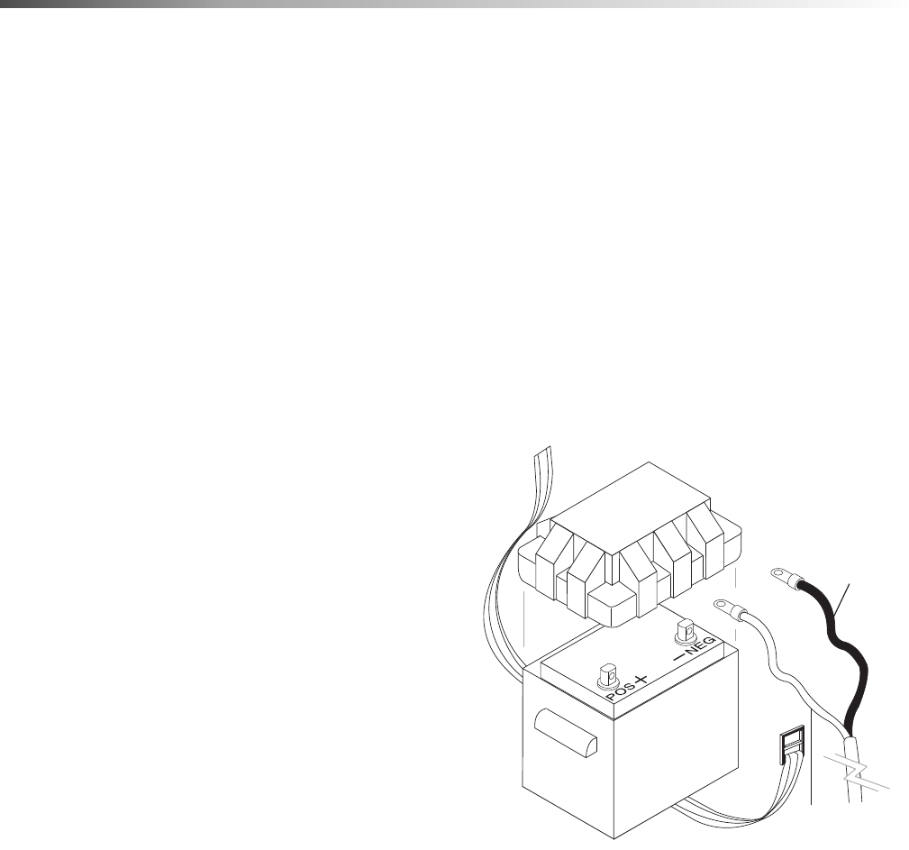
Battery
WARNING: Batteries generate explosive gases
during normal battery operation. DO NOT expose
the battery to flame or sparks as these gases may
ignite.
WARNING: Battery fluid is highly acidic. If battery
fluid contacts skin or clothing, wash immediately
with soap and water. If battery fluid enters eye,
immediately flood eye with running cold water for
at least 15 minutes and get immediate medical
attention.
1. Install battery (battery not included) in battery box
as shown. Use a standard automotive battery
minimum 500 CCA (Cold Cranking Amps). It is
recommended that a dual cell battery (a battery
with a separate cell for emergency starting) be
used.
2. To reduce the possibility of sparking attach the
battery cables in the following order. First attach
the positive battery cable (red) to the positive “+”
terminal of the battery. Next, attach the negative
battery cable (black) to the negative “-” terminal of
the battery. To disconnect the battery, remove the
cables in the opposite order as installed.
3. Install battery box lid and secure with strap
provided.
Hotsy 1200 8.914-366.0 - R
Black
Cable
Red
Cable

13
Operations
Oil Burner
Burner Air Adjustment: The oil burner is preset for
operation at altitudes below 3000 feet. If operated at
higher altitudes, it may be necessary to adjust the air
band setting. Adjust the air band for a #1 or #2 smoke
spot on the Baccarat scale.
Hotsy Crossfire Oil Burner
Burner Air Adjustment: The oil burner on this
machine is preset for operation at altitudes below 500
feet. If operated at higher altitudes, it may be necessary
to adjust the air band for a #1 or #2 smoke spot on the
Bacharach scale.
To adjust, start machine and turn burner ON. Loosen
two locking screws found on the air band and close air
band until black smoke appears from burner exhaust
vent. Note air band position. Next, slowly open the air
band until white smoke just starts to appear. Turn air
band halfway back to the previously noted position.
Tighten locking screws.
Hotsy Crossfire Oil Burner
CAUTION: If white smoke appears from burner
exhaust vent during start-up or operation, discon-
tinue use and readjust air bands.
NOTE: If a flue is installed, have a professional
serviceman adjust your burner for a #1 or #2 smoke
spot on the Bacharach scale.
Gasoline Engine
This gasoline engine is preset for operation at altitudes
below 3000 feet above sea level. If operated at higher
altitudes, it may be necessary to install a high altitude
main jet in the carburetor. Contact an authorized engine
sales and service center for details.
Water Supply
This machine is designed to be connected to a pressur-
ized (20 to 100 PSI) water supply, capable of main-
taining a minimum of 6.0 GPM. If it is necessary to use
a gravity feed water tank, the following plumbing modi-
fications will be required.
A 1/2" NPT 3-way ball valve will need to be installed in
the water inlet line. Hotsy recommends the use of Watts
Regulator Valve #1/2 B6780 M1 (Hotsy P/N 921363)
for this application. With this valve in place this machine
will be capable of using both a pressurized or gravity
feed water supply without additional modifications. For
proper operation it is important that the valve be fully
open for its intended supply. This will prevent air from
being drawn into the system from the non active
source. Also the pressure supply must still be
connected to the float tank. The connection of a pres-
surized supply directly to the 3-way valve will prevent
detergent from being drawn into the system.
Hotsy 1200 8.914-366.0 - R
Reference Numbers
Air Band Locking Screws
Air Band

14
Operations
Operation Instructions
Before Starting
WARNING: Check hoses, fittings, wand, trigger gun
and fuel connections daily for signs of wear, cracks
and looseness, replace as required.
1. Read all manuals provided with this pressure
washer. Become familiar with location and function
of all operating and safety controls.
2. Connect the water supply hose to the float tank
water inlet (standard garden hose connector). The
water faucet and supply hose must be capable of
providing 6.0 GPM.
3. Fill the burner fuel tank. Use kerosene, #1 grade
home heating oil, #1 or #2 diesel fuel.
DO NOT USE GASOLINE.
4. Fill the gasoline tank. Use lead free gasoline
minimum 86 octane. DO NOT use gasoline
containing more than 10% ethanol, 15% MTBE, or
5% methanol.
5. Check pump and engine oil levels.
6. If detergents are to be used, only use detergent for
pressure washers. Follow instructions on detergent
container.
IMPORTANT: Before installing the pressure nozzle
on initial start-up, turn on the water supply and
allow water to run from the end of the wand until
clear to prevent the pressure nozzle from clogging.
IMPORTANT: If the pressure washer has not been
used for an extended period of time, remove the
pressure nozzle from the end of the wand and turn
on the water supply. Allow water to run from the
end of the wand until clear.
7. Install the proper pressure nozzle for your cleaning
needs on end of wand.
IMPORTANT: The trigger gun provided with this
pressure washer is equipped with a manual trigger
lock to prevent accidental operation of the trigger
gun. The manual trigger lock should be used
whenever the trigger gun is not in use.
Fuel Pump
Some 1200 models are equipped with an electric fuel
pump which operates only when the engine is running.
The pump is primed when the key switch is held in the
start position. In the event that the engine stalls for any
reason the fuel pump will shut off.
WARNING: The fuel pump installed on this machine
has been adjusted at the factory to provide a
maximum pressure of 1.3-1.7 PSI at the pump
outlet. Whenever the fuel pump is replaced the new
pump must be adjusted using the following proce-
dure:
1. Place the ignition switch in the OFF position.
2. Disconnect the fuel line from the engine mounted
fuel filter and connect a fuel pump pressure gauge
(0-5 PSI) to the fuel pump discharge line.
3. Turn the ignition key to the start position and
observe pressure gauge. Pressure must be set to
between 1.3 and 1.7 PSI. It will be necessary to
bleed off accumulated pressure in line prior to each
gauge reading. Turn screw on top of fuel pump to
adjust pressure (CCW to decrease, CW to
increase).
4. After adjustment, reconnect fuel line to engine
mounted fuel filter and start machine. Check for
fuel leakage and tighten fittings/clamps as
required.
Hotsy 1200 8.914-366.0 - R
Manual Trigger Lock
Pressure
Nozzle

15
Operations
To Start
DANGER: DO NOT point wand or spray gun at
yourself or at any person. Bodily injury may result
from water under high pressure.
IMPORTANT: The water must be turned on before
starting. Running the pump dry will cause damage
and void warranty.
IMPORTANT: DO NOT allow the machine to run with
trigger gun closed for more than 3 minutes at any
time or damage to pump may occur.
1. Turn water ON.
2. Hold wand firmly with trigger gun in the closed
position.
3. Turn fuel shut-off valve counterclockwise (CCW) to
open. Move choke lever to full choke position.
Choke may not be needed on warm engine.
4. Move throttle control to half throttle.
5. Turn key on engine clockwise (CW) hold until
engine starts. DO NOT crank engine for longer
than 15 seconds at any one time or starter damage
may occur. If the engine does not start, it may have
air in the gas lines and be unable to pull gasoline
from the fuel tank. This symptom may appear if the
engine has not been run recently or had been run
until all gasoline was depleted from gas lines.
6. When the engine starts, move choke lever until
engine runs smoothly. Then move throttle control
to full throttle. When engine warms, move choke to
no choke position.
IMPORTANT: To allow for proper battery charging
and AC generator operation the throttle control
MUST be kept in full throttle position as soon as
choke lever is placed in no choke position.
7. Holding wand firmly, squeeze the trigger gun open.
Allow air to purge from system.
8. If hot water is desired, adjust the thermostat to
proper temperature. Close the trigger gun and turn
burner switch ON.
IMPORTANT: The throttle control must be in the full
throttle position or damage to the AC generator or
burner may result.
9. Open the trigger gun. The burner will fire immedi-
ately with a puff of smoke. If smoke continues,
refer to the Troubleshooting Guide in this manual.
When the trigger gun is closed or the temperature
setting is reached, the burner will automatically
turn off.
Hotsy 1200 8.914-366.0 - R

16
Operations
Detergents & General Washing Techniques
WARNING: Some detergents may
be harmful if inhaled or ingested,
causing severe nausea, fainting
or poisoning. The harmful
elements may cause property
damage or severe injury.
STEP 1: Use detergent designed
specifically for pressure washers.
Household detergents could
damage the pump. Prepare
detergent solution as required by the
manufacturer. Fill a container with
pressure washer detergent. Place
the filter end of detergent suction
tube into the detergent container.
STEP 2: With the engine running, pull trigger to operate
machine. Liquid detergent is drawn into the machine
and mixed with water. Apply detergent to work area. Do
not allow detergent to dry on surface.
IMPORTANT: You must flush the detergent after
each use by placing the suction tube into a bucket
of clean water, open detergent valves then run the
pressure washer for 1-2 minutes.
Thermal Pump Protection
If you run your pressure washer for 3-5 minutes without
pressing the trigger on the spray gun, circulating water
in the pump can reach high temperatures. When the
water reaches this temperature, the pump protector
engages and cools the pump by discharging the warm
water onto the ground. This thermal device prevents
internal damage to the pump.
Cleaning Tips
Pre-rinse cleaning surface with fresh water. Place
detergent suction tube directly into cleaning solution
and apply to surface at low pressure (for best results,
limit your work area to sections approximately 6 feet
square and always apply detergent from bottom to top).
Allow detergent to remain on surface 1-3 minutes. Do
not allow detergent to dry on surface. If surface
appears to be drying, simply wet down surface with
fresh water. If needed, use brush to remove stubborn
dirt. Rinse at high pressure from top to bottom in an
even sweeping motion keeping the spray nozzle
approximately 1 foot from cleaning surface. Use over-
lapping strokes as you clean and rinse any surface. For
best surface cleaning action spray at a slight angle.
Recommendations:
• Before cleaning any surface, an inconspicuous
area should be cleaned to test spray pattern
and distance for maximum cleaning results.
• If painted surfaces are peeling or chipping, use
extreme caution as pressure washer may
remove the loose paint from the surface.
• Keep the spray nozzle a safe distance from the
surface you plan to clean. High pressure wash
a small area, then check the surface for
damage. If no damage is found, continue to
pressure washing.
CAUTION - Never use:
• Bleach, chlorine products and other corrosive
chemicals
• Liquids containing solvents (i.e., paint thinner,
gasoline, oils)
• Tri-sodium phosphate products
• Ammonia products
• Acid-based products
These chemicals will harm the machine and will
damage the surface being cleaned.
Rinsing
It will take a few seconds for the detergent to clear.
Apply safety latch to spray gun and close detergent
valve. Select and install the desired high pressure
nozzle.
Hotsy 1200 8.914-366.0 - R
WARNING

17
Operations
Shutdown Instructions
1. If detergents were used, draw clear water through
the system to purge detergent.
2. If burner was used, turn OFF burner switch, and
allow pump to run cold water through coil.
3. Move throttle control to idle position.
4. Turn key on engine counterclockwise (CCW) to
OFF position.
5. Turn OFF fuel shut-off valve.
6. Turn OFF water supply.
7. Squeeze trigger gun open to relieve system
pressure.
Storage
DANGER: Do not store flammable liquids (gasoline,
solvents, etc.) near pressure washer, or in non-
ventilated areas.
Protect from freezing by storing in a heated area, or by
flushing the system with antifreeze. To flush the
system, fill the float tank with antifreeze and remove
spray nozzle from wand. Start the machine and allow it
to run until antifreeze flows from the end of the wand.
Place end of wand into float tank and circulate the anti-
freeze through system for several minutes. Open and
close the trigger gun several times to circulate anti-
freeze through the unloader valve. Place detergent line
into the float tank. Open the detergent metering valve to
draw antifreeze into the detergent system.
If the pressure washer is not to be used for a consider-
able length of time, it is recommended to flush the
system with antifreeze for rust protection.
Hotsy 1200 8.914-366.0 - R

18
Maintenance
WARNING: Unauthorized machine modification or
use of non-approved replacement parts may cause
personal injury and/or property damage and will
void the manufacturer warranty.
Pump
Use HOTSY Pump Oil (8.923-422.0) or equivalent
10W-40 non-detergent oil for pump crankcase.
Crankcase must be filled to the full mark on the dipstick
or to center of sight glass window found on the rear of
the pump. During the break-in period, make sure the oil
is changed after the first 25 hours of operation. After
that, replace oil every 3 months or 300 hours,
whichever comes first.
DO NOT:
1. Pump acids.
2. Fail to winterize in freezing temperatures.
3. Allow pump to run dry.
4. Allow machine to run with trigger gun closed for
more than 3 minutes at any one time or damage to
pump may occur.
DO:
1. Use a water softener on the water system if known to
be high in mineral content.
2. Use only high quality detergents and follow manufac-
turer's mix recommendations.
3. Immediately after using detergent solutions the sys-
tem should be flushed thoroughly with clear water.
4. Clean strainer screen on detergent line periodically.
Unloader Valve
WARNING: The unloader valve on this pressure
washer has been factory set and sealed and is a
field nonadjustable part. Tampering with the
factory setting may cause personal injury and/or
property damage, and will void the manufacturer
warranty.
Burner Fuel Filter
Drain water that has accumulated in fuel filter and clean
filter element as needed.
Heating Coil
Coil De scaling: In hard water areas, scale buildup
within the heating coil will occur. Scale deposits will
decrease the water temperature rise and may eventu-
ally clog the heating coil. Contact your local service
center when de scaling is needed.
Coil De sooting: Poor grades of fuel oil or inadequate
combustion air will cause heavy soot buildup on the
outside surface of the heating coil. This will restrict the
airflow through the coil, further aggravating the soot
buildup. Contact your local service center when
de sooting is needed.
Engine
Refer to engine manual provided with this pressure
washer for recommended maintenance.
Oil Burner Blower Motor
The motor bearings are permanently lubricated and will
not require any additional lubrication.
Battery
Refer to battery manufacturer’s literature for recom-
mended maintenance
Hotsy 1200 8.914-366.0 - R

19
Maintenance
Troubleshooting
PROBLEM POSSIBLE CAUSE SOLUTION
ENGINE WILL
NOT RUN
No fuel Replenish supply.
Low battery Charge battery.
Poor battery cable connection Clean battery terminals and check cables.
Refer to provided engine manual for additional troubleshooting.
NO WATER FROM
PRESSURE
NOZZLE
Pressure nozzle clogged Clean pressure nozzle.
Inlet water screen clogged Clean.
Pumping sucking air
Fill the detergent container. Check for loose hose
clamps or fittings.
POOR OR NO
DETERGENT
FLOW
Low detergent level Replenish supply.
Detergent screen clogged Clean.
Detergent metering valve not opening Check that handle or knob is not slipping on shaft.
Pressure nozzle clogged Clean.
LOW PRESSURE
FROM SPRAY
NOZZLE.
Inlet clogged Clean
Spray nozzle worn or incorrect size Replace.
Inadequate water supply Increase water supply.
Pump sucking air
Fill the detergent container. Check for loose hose
clamps or fittings.
UNLOADER
VALVE CYCLES
WHEN TRIGGER
GUN IS OPEN
OR CLOSED
Air in system Open and close trigger gun several times.
Defective unloader valve Repair or replace.
Water leak between unloader valve
and trigger gun.
Check fittings, hose and trigger gun for leaks. Repair
or replace.
BURNER
WILL NOT IGNITE
WHEN TRIGGER
GUN IS OPEN
No fuel Replenish supply.
Adjustable thermostat set too
low Defective pressure switch
Electrodes are dirty or out of adjust-
ment No AC generator output
Raise temperature setting. Repair or replace.
Refer to OIl Burner Manual provided with machine.
Check AC generator.
BURNER
SMOKES OR
HAS
OBNOXIOUS
ODOR
Air bands need to be adjusted
Improper fuel
Readjust. Refer to Oil Burner Section under Instal-
lation.
Use kerosene, #1 Grade Home Heating Oil, #1 or #2
Diesel Fuel.
DO NOT USE GASOLINE.
Hotsy 1200 8.914-366.0 - R

20
Maintenance
PROBLEM POSSIBLE CAUSE SOLUTION
MACHINE
SMOKES
WHILE
BURNER UNIT
IS RUNNING
OR
UNIT SMOKES
AT COLD-START
ONLY WHEN
BURNER
IS OFF
Improper fuel or water in fuel Drain tank and replace contaminated fuel
Improper air adjustment Readjust air bands on burner assembly
Fuel pressure is low <140 psi for
burner
Adjust fuel pump pressure to specifications
Burner nozzle is plugged or dirty
Replace nozzle. Check parts breakdown
for nozzle size
Burner nozzle spray pattern is faulty
Replace nozzle. Check parts breakdown
for nozzle size
Heavy accumulation of soot on coils
and burner assembly
Remove coils and burner assembly,
clean thoroughly Call local dealer
Misaligned electrode setting Realign electrodes to specifications
MACHINE
SMOKES
WHILE
BURNER UNIT
IS RUNNING
OR
UNIT SMOKES
AT COLD-START
ONLY WHEN
BURNER
IS OFF
CONTINUED
Obstruction in smoke stack
Check for insulation blockage or other
foreign objects
Low engine RPM Increase RPM to correct specs. See serial plate
Fuel Pressure is too high for clean
burn (fuel PSI above 140 and below
200) and smokes when burner is off
Reduce fuel pressure PSI/Increase air band set for
cleaner without max water heat loss
Hotsy 1200 8.914-366.0 - R

21
Maintenance
IMPORTANT
If the pressure washer demonstrates other symptoms or the corrective actions
listed do not correct the problem, contact the local authorized Hotsy Service
Center. The Hotsy Service Center can be identified by visiting www.hotsy.com
or by calling 1-800-525-1976.
When ordering from your dealer, please provide the following:
Model Number: _______________________________________
Machine Serial Number: ________________________________
Component Part Number: _______________________________
Description: __________________________________________
Hotsy 1200 8.914-366.0 - R

22
Notes
Hotsy 1200 8.914-366.0 - R

23
Parts
Parts
(1.110-533.0, 1.110-557.0, 1.110-558.0, 1.110-535.0,
1.110-536.0, 1.110-537.0, 1.110-043.0, 1.110-538.0,
1.110-044.0, 1.110-539.0)
HOTSY 1200
Hotsy 1200 8.914-366.0 - R

24
Coil & Chassis - 1260SSG, 1270SSG, 1280SSG, 1285SSG 1290SSG
Hotsy 1200 8.914-366.0 - R
See
Gasoline
Tank For
Detail
To Fuel
Tank
24
23
22
21
20
19
13
104
17
16
18
33
34
14
7
9
11
10
1
6
5
36
2
4
37
84
87
80,81
75
49
83 83
49
92
88
85
33
8
44
43
96
74
See
Fuel Tank
For
Detail
See
Float
Tank For
Detail
See
Control
Box For
Detail
See
Coil Outlet
Assy. For
Detail
103
12
102
See
Hose &
Spray Gun
Assy. For
Detail
See Wire
Routing
Illus. For
Positioning
See
Burner
Assy. For
Detail
88
86
101
112
114
115
91
89143660-3
See
Gasoline
Tank For
Detail
To Fuel
Tank
24
23
22
21
20
19
13
104
17
16
18
33
34
14
7
9
11
10
1
6
5
36
2
4
37
84
87
80,81
75
49
83 83
49
92
88
85
33
8
44
43
96
74
See
Fuel Tank
For
Detail
See
Float
Tank For
Detail
See
Control
Box For
Detail
See
Coil Outlet
Assy. For
Detail
103
12
102
See
Hose &
Spray Gun
Assy. For
Detail
See Wire
Routing
Illus. For
Positioning
See
Burner
Assy. For
Detail
88
86
101
112
114
115
91

25Hotsy 1200 8.914-366.0 - R
Power Platform - 1260SSG, 1270SSG, 1280SSG, 1285SSG 1290SSG
To
Float
Tank
To
Detergent
Valve
26
69
27
29
30
49
50
46
40
47
67
58
41
51
52
53
62
57
55
32
79
31
28
35
66
56
42
45
44
43
39
60
68
64
63
61
38
70
73
72
71
76
78
90
8
80
81
59
44
3
9
9
59
83
44
59
94
91
90
97
8
82
14
96
93
65
48
98
50
95
25
91
Reversed
View
15
65
77
1260SSG
12HP
Vanguard
Only
Honda
Only
Honda Only
100
For
Honda
Engine
Only
To
Gasoline
Tank
Power Platform
with Generator
99
105
108
111
110
109
110
110 113
107
110
99
106
89
64
63
To Carbon
Canister
Purge Side
111
For
Details
See Pump
Assy.

26
Parts - 1260SSG, 1270SSG, 1280SSG, 1285SSG 1290SSG
REF PART NO. QTY DESCRIPTION NOTES
1 8.912-121.0 1 CHASSIS ASSEMBLY, HOTSY 1200 SERIES
2 8.706-600.0 1 BOX, BATTERY, M-100
3 9.802-814.0 1 WASHER, 3/8" LOCK
4 9.802-708.0 2 SCREW, 5/16"-18 X 3/4"
5 9.802-832.0 1 BOLT, 5/16" X 2 3/4" WHIZLOCK
6 8.912-129.0 1 STRAP, COIL, HOTSY 1200
7 8.706-547.0 1 GROMMET, 1/2" X 1" X 1/2"
8 9.802-778.0 14 NUT, 5/16" FLANGE, WHIZ LOC
9 9.802-065.0 2 GROMMET, 1-5/16" RUBBER
(1260SSG)
- 9.802-065.0 3 GROMMET, 1-5/16" RUBBER
(1270SSG, 1280SSG,
1290SSG)
10 9.802-067.0 7 BUMPER PAD, ENGINE
11 9.802-066.0 7 PAD, SOFT RUBBER, 50 DURO
12 9.802-778.0 2” NUT, 3/8" WHIZ
13 8.751-741.0 1 INSULATION PANCAKE, 14"
14 8.706-733.0 2 BUSHING, 1/2" SNAP
15 8.900-282.0 1 LABEL, FACTORY SET RPM
16 8.904-536.0 4 STRAPPING, 1/2" X 48" W/CLAMPS
17 9.802-188.0 1 VALVE, METERING, 1/4" HOSE
18 8.706-547.0 3 GROMMET, 1/2” X 1" X 1/”
19 8.911-328.0 1 LID, 18" OD X 10" ID,WELDMENT
20 8.717-442.0 1
INSULATION, TOP HEAD, 18" OD X 8 ID,
FIBERGLASS
21 8.719-935.0 1 RING, INSULATION RETAINER, 18" TOP HAT
22 8.911-930.0 1 COIL, 18"
- 8.912-098.0 1 COIL, 18" SUPER DUTY
23 8.717-446.0 1 INSULATION, BLANKET, FIBERGLASS
24 8.911-331.0 1 WRAP, COIL OUTER ASSEMBLY, HOTSY 1200
25 8.707-019.0 1 HOSE BARB, 1/2" BARB X 3/8" MNPT, BRASS HEX
26 8.911-247.0 1 GUARD, PULLEY BELT
27 8.911-248.0 1 WELDMENT, GEN. BELT GUARD
(1270SSG,
1280SSG,1290SSG)
- 8.911-255.0 1 WELDMENT, GEN. BELT GUARD 1260SSG
(1285SSG)
28 8.716-610.0 1 GENERATOR, 2FSM2PC-1/A, WINCO
29 8.918-425.0 1 HOSE, 3/8" X 29", 2 WIRE, PRESSURE LOOP
- 8.918-426.0 1 HOSE, 3/8" X 32", 2 WIRE, (SUPER DUTY ONLY)
30 9.802-038.0 1 NIPPLE, 1/2" JIC X 1/2" MPT PIPE
31 8.706-236.0 1 TEE, 1/2" STREET
32 8.706-243.0 1 PLUG, 1/2" SQUARE HEAD, GALVANIZED
33 8.719-000.0 7 WASHER, 5/16" X 1-1/4" FENDER, SAE
34 9.802-756.0 3 BOLT, 5/16" X 1" NC HH, WHIZ LOC
35 8.752-150.0 1 Pc CORD, MOLDED, 14/3 SJEOW
36 8.753-358.0 1 CABLE, BATTERY, 61" EYE TO EYE RED
Hotsy 1200 8.914-366.0 - R

27Hotsy 1200 8.914-366.0 - R
1260SSG, 1270SSG, 1280SSG, 1285SSG 1290SSG
REF PART NO. QTY DESCRIPTION NOTES
37 8.753-359.0 1 CABLE, BATTERY, 61" EYE TO EYE BLACK
38 9.803-545.0 1 GROMMET, 2-1/8" X 2-7/8" X 7/16" RUBBER
39 9.802-716.0 4 BOLT, 5/16" X 2" NC HH
(1260SSG)
- 9.802-728.0 5 BOLT, 3/8" X 2" NC HH
40 9.802-207.0 1 CLIP, .25 ID ROUND
41 8.911-249.0 1 WELDMENT, BELT GUARD BACK PLATE
(1280SSG, 1290SSG)
- 8.911-254.0 1 WELDMENT, BELT GUARD BACK PLATE
(1260SSG, 1270SSG)
42 8.912-125.0 1 BRACKET, GEN. TAKE UP, HOTSY 1200
43 9.803-560.0 2 SCREW, 3/8" X 2" HH NC, WHIZ LOC
44 9.802-807.0 18 WASHER, 3/8" SAE FLAT
45 9.802-789.0 1 NUT, 3/8" HEX, NC
46 9.802-672.0 1
MUFFLER, EXHAUST, BRIGGS VANGUARD HI-
RIGHT
(1260SSG)
- 8.718-040.0 1 MUFFLER, VANGUARD
(1285SSG)
- 8.750-497.0 1 MUFFLER, HONDA GX630/660, K1, RIGHT
47 8.754-819.0 1 ENGINE, VANGUARD, 18HP
(1260SSG)
- 8.752-149.0 1 ENGINE, HONDA, GX630R, NO THROTTLE
(1270SSG, 1280SSG,
1290SSG)
- 8.715-067.0 1 ENGINE, VANGUARD, 21HP
(1285SSG)
48 9.802-867.0 4 GUARD, MUFFLER, BRIGGS
(1260SS/G)
- 8.749-367.0 4 GUARD, MUFFLER, VANGUARD
(1285SS/G)
49 6.390-126.0 4 CLAMP, HOSE, .46 - .54 ST
50 8.750-737.0 1 ADAPTER, M20-1.5 X 3/8" FPT (HONDA)
- 8.706-993.0 1 ADAPTER, 3/8' X 3/8' (VANGUARD)
51 9.802-809.0 1 WASHER, 1/2" FLAT, SAE
52 9.803-517.0 1 WASHER, 1/2" LOCK
53 9.802-790.0 1 NUT, 1/2" HEX, NC
54 9.802-789.0 6 NUT 3/8 HEX
(SUPER DUTY ONLY)
55 9.802-254.0 22" HOSE, 1/4" PUSH-ON
(HONDA ENGINE ONLY)
56 8.933-005.0 1 PUMP, 12V FUEL, FACET
(HONDA ENGINE ONLY)
57 8.718-582.0 2 BOLT, 1/4" X 1/2" NC HH
58 9.802-039.0 1 ELBOW, 1/2" JIC X 3/8", 90°
59 9.802-779.0 15 NUT, 3/8" ESNA, NC
60 9.802-762.0 2 SCREW, 10/32" X 1-1/4"
(HONDA ENGINE ONLY)
61 8.911-830.0 1 SLIDER, PUMP, WELDMENT
62 9.802-740.0 1 BOLT, 1/2" X 3-1/2" NC HH
63 8.718-937.0 2
SCREW, #8 X 3/4", PHILLIPS, ZINC PLATED, HEX,
TEK
64 9.802-203.0 2 CLAMP, 1/2" RO-CLIP, KLEINHUIS
65 9.802-830.0 4 SCREW, 1/4-20 X 1/2" HH
66 8.706-955.0 2 HOSE BARB, 1/4" BARB X 1/8" ML PIPE, 90°
(HONDA ENGINE ONLY)
67 8.918-423.0 1 HOSE, 3/8" X 22", 2 WIRE, PRESSURE LOOP
- 8.918-422.0 1 HOSE, 3/8 X 20", 2 WIRE PRESSURE LOOP
(SUPER DUTY ONLY)

28
1260SSG, 1270SSG, 1280SSG, 1285SSG 1290SSG
REF PART NO. QTY DESCRIPTION NOTES
68 8.912-123.0 1 PLATFORM, POWER
(1270SSG, 1280SSG,
1290SSG)
- 8.912-130.0 1 PLATFORM, POWER 1260SSG
(1285SSG)
69 9.803-277.0 4 BOLT, 5/16" X 1/2", NC WHIZ LOC
70 - - BELT
SEE SPECIFICATIONS
PAGE
71 - - PUMP PULLEY
SEE SPECIFICATIONS
PAGE
72 - - MOTOR PULLEY
SEE SPECIFICATIONS
PAGE
73 - - MOTOR BUSHING
SEE SPECIFICATIONS
PAGE
74 8.719-946.0 1 HANGER, HOSE
75 9.800-020.0 1 LABEL, WATER INLET
(ALL EXPECT
SUPER DUTY)
76 - - ENGINE BUSHING
SEE SPECIFICATIONS
PAGE
77 9.802-754.0 4 SCREW, 1/4" X 1/2" WHIZ LOC
(VANGUARD)
78 - - ENGINE PULLEY
SEE SPECIFICATIONS
PAGE
79 - - PUMP BUSHING
SEE SPECIFICATIONS
PAGE
80 9.802-776.0 6 NUT, 5/16" ESNA
81 8.718-980.0 10 WASHER, 5/16" FLAT, SAE
82 9.802-695.0 2 NUT, 10/32" KEPS
83 9.802-252.0 6 ft. HOSE, 1/4" X 1/2" BRAIDED VINYL
84 9.802-778.0 2 NUT, 5/16" WHIZ LOC
85 8.704-659.0 2 LABEL, HOTSY LOGO 5 X 11
86 9.802-807.0 1 WASHER, 3/8" FLAT
87 8.900-925.0 1 LABEL, HOTSY 1200 SERIES
88 8.718-940.0 2 SCREW, #10 X 3/4, TEK SS
89 9.802-259.0 11" HOSE, 1/2" PUSH-ON
90 8.932-965.0 2 LABEL, EXPOSED PULLEYS
91 9.800-006.0 4 LABEL, HOT W/ARROWS
92 8.707-058.0 1 STRAINER, 1/4" BRASS W/CHECK VALVE
93 9.802-868.0 2 BRACE, VANGUARD MUFFLER
94 - - ENGINE BELT
SEE SPECIFICATIONS
PAGE
95 9.802-126.0 1 PLUG, 1/2" JIC FLARE
96 9.802-252.0 24” HOSE, 1/4" X 1/2" BRAIDED VINYL
97 9.802-691.0 1 EXHAUST, DEFLECTOR
98 9.802-794.0 2 NUT, 1/4" X 12, CAGE
(VANGUARD ENGINE
ONLY)
99 8.917-015.0 1 LABEL, REGULATION 4442.6
100 8.718-732.0 1 SCREW, 12-14 X 3/4" PL, SELFOR, HEX
101 9.802-814.0 3 WASHER, 3/8 SPLIT RING LOCK
(SUPER DUTY ONLY)
Hotsy 1200 8.914-366.0 - R

29Hotsy 1200 8.914-366.0 - R
1260SSG, 1270SSG, 1280SSG, 1285SSG 1290SSG
REF PART NO. QTY DESCRIPTION NOTES
102 8.718-674.0 6 BOLT, 3/8" X 2-1/4", GR 8.2
103 9.802-781.0 6 NUT, 3/8" WHIZ
104 8.911-950.0 1 INSULATION RETAINER
105 8.753-269.0 1 REDUCER, 1/4 X 3/16
(VANGUARD)
106 9.802-151.0 1 SWIVEL, 1/2" JIC FEM, PUSH-ON
107 8.711-785.0 8” HOSE 3/8" PUSH-ON
(HONDA ONLY)
108 8.753-270.0 1 REDUCER, 1/4 X 3/8
(HONDA ONLY)
109 9.802-254.0 4 HOSE 1/4" PUSH-ON/FT
110 8.753-066.0 2 #7 CLAMP
(HONDA)
- - 3 #7 CLAMP
(VANGUARD)
111 8.753-065.0 2 #10 CLAMP
(HONDA)
112 8.706-728.0 1 BUSHING, 1-3/8" SNAP
113 8.718-781.0 1 SCREW, PAN HEAD
114 8.921-830.0 1 PLATE, GAS
115 8.921831.0 1 PLATE, DIESEL

30
Coil & Chassis - 1260SS, 1270SS, 1280SS, 1285SS, 1290SS
Hotsy 1200 8.914-366.0 - R
See
Float
Tank For
Detail
To Fuel
Tank
24
23
22
20
19
13
17
16
18
33
34
14
7
9
82
102
1
6
5
36
2
4
37
See Wire
Routing
Illus. For
Positioning
40
75
For
Detail See
Burner
Assy.
83
33
8
86
10
11
Honda
Engine Only
(Reversed
View)
80
81
49
49
80
79
90
See Coil
Outlet
Assembly
For Detail
21
Reversed
View
92
57
41
94
95
Super Duty
Option
See
Gasoline
Tank For
Detail
97
82
12
84
See
Fuel Tank
For
Detail
See
Control
Box For
Detail
75
44
77
34
108
109
110
50

31Hotsy 1200 8.914-366.0 - R
Power Platform - 1260SS, 1270SS, 1280SS, 1285SS, 1290SS
89143660-11
To
Gasoline
Tank
To
Float
Tank
To
Detergent
Valve
26
66
48
29
30
49
91
91
46, 78,
88,100
35
47
45
58
41
42
43
44
53
57
55
32
25
31
60
56
59
59
39
14
65
64
63
15
61
38
52
54
28
28
67
68
74
50
62
8
7
For
Honda
Engines
Only
28
59
8
9
See
Pump Assy.
For
Detail
50
87
76
70
71
88
27
70
72
99
51
52
53
1260SS
93
96
51
101
107
105
107
103
106
103
103
98
89
104
85
Power Platform
Vanguard
only
Honda
only
To Carbon
Canister
Purge Side

32
Parts - 1260SS, 1270SS, 1280SS, 1285SS, 1290SS
REF PART NO. QTY DESCRIPTION NOTES
1 8.912-121.0 1 CHASSIS ASSEMBLY, HOTSY 1200 SERIES
2 8.706-600.0 1 BOX, BATTERY, M-100
3 8.718-980.0 10 WASHER, 5/16" X 1" FLAT, SAE
(1260SS)
--4 -
(1270SS, 1280SS,
1290SS)
4 9.802-708.0 2 SCREW, 5/16"- 18 X 3/4"
5 9.802-832.0 1 BOLT, 5/16" X 2 3/4" WHIZLOCK
6 8.912-129.0 1 STRAP, COIL, HOTSY 1200
7 - - ENGINE PULLEY
SEE SPECIFICATIONS
PAGE
8 9.802-778.0 14 NUT, 5/16" FLANGE, WHIZ LOC
9 9.802-065.0 3 GROMMET, 1-5/16" RUBBER, DRUM CLEANER
10 9.802-067.0 6 BUMPER PAD, ENGINE
11 9.802-066.0 6 PAD, SOFT RUBBER, 50 DURO
12 9.802-778.0 2 NUT, 5/16 WHIZ
13 8.718-207.0 1 INSULATION PANCAKE, 18
14 8.706-733.0 2 BUSHING, 1/2" SNAP
15 9.802-744.0 4 BOLT, 10MM X 20MM, HH
16 8.904-536.0 4 STRAPPING, 1/2" X 48" W/CLAMPS
17 9.802-188.0 1 VALVE, METERING, 1/4" HOSE
18 9.802-064.0 3 GROMMET, RUBBER, NOZZLE HOLDER
19 8.911-328.0 1 LID, 18" OD X 10" ID, WELDMENT
20 8.717-442.0 1
INSULATION, TOP HEAD, 18" OD X 8 ID,
FIBERGLASS
21 8.719-935.0 1 RING, INSULATION RETAINER, 18" TOP HAT
22 8.911-930.0 COIL, 18"
- 8.912-098.0 1 COIL, 18" SUPER DUTY ONLY
23 8.717-446.0 1 INSULATION, BLANKET, FIBERGLASS
24 8.911-331.0 1 WRAP, COIL OUTER ASSEMBLY, HOTSY 1200
25 - - BELTS
SEE SPECIFICATIONS
PAGE
26 8.911-250.0 1 BELT GUARD, BACK PLATE 1260SS
- 8.911-252.0 1 BELT GUARD, BACK PLATE
(HONDA MODELS &
SUPER DUTY OPTION)
27 8.911-251.0 1 GUARD, FRONT BELT 1260SS
- 8.911-253.0 1 GUARD, FRONT BELT
(HONDA MODELS &
SUPER DUTY OPTION)
28 9.802-807.0 6 WASHER, 3/8" SAE, FLAT
(1260SS)
--10 -
(1270SS, 1280SS,
1290SS)
29 8.918-425.0 1 HOSE, 3/8" X 29", 2 WIRE, PRESSURE LOOP
- 8.918-426.0 1 HOSE, 3/8" X 32", 2 WIRE,
(SUPER DUTY ONLY)
30 9.802-038.0 1 NIPPLE, 1/2" JIC X 1/2” MPT PIPE
31 8.706-236.0 1 TEE, 1/2" STREET
32 8.706-243.0 1 PLUG, 1/2" SQUARE HEAD, GALVANIZED
Hotsy 1200 8.914-366.0 - R

33Hotsy 1200 8.914-366.0 - R
1260SS, 1270SS, 1280SS, 1285SS, 1290SS
REF PART NO. QTY DESCRIPTION NOTES
33 8.719-000.0 7 WASHER, 5/16" X 1-1/4" FENDER, SAE
34 9.802-756.0 3 BOLT, 5/16" X 1" WHIZ, NC, HH
35 8.709-089.0 1 HOSE CLAMP
36 8.753-358.0 1 CABLE, BATTERY, 61" EYE TO EYE RED
37 8.753-359.0 1 CABLE, BATTERY, 61" EYE TO EYE BLACK
38 9.803-544.0 1 GROMMET, 2-1/8" X 2-7/8” X 7/16" RUBBER
39 9.802-716.0 4 BOLT, 5/16" X 2" NC HH
(1260SS)
- 9.802-728.0 4 BOLT, 3/8" X 2" NC HH
(1270SS,1280SS,
1290SS)
40 9.802-700.0 2 BOLT, 1/4" X 3/4" NC HH
(HONDA ONLY)
41 9.802-809.0 2 WASHER, 1/2" FLAT, SAE
42 9.803-517.0 1 WASHER, 1/2" LOCK
43 9.802-790.0 1 NUT, 1/2" HEX, NC
44 9.802-740.0 1 BOLT, 1/2" X 3-1/2" NC HH
45 8.918-423.0 1 HOSE, 3/8" X 22", 2 WIRE, PRESSURE LOOP
- 8.918-422.0 1 HOSE 3/8" X 20", 2 WIRE
(SUPER DUTY ONLY)
46 9.802-672.0 1
MUFFLER, EXHAUST, BRIGGS VANGUARD HI-
RIGHT
(1260SS)
- 8.718-040.0 1 MUFFLER, VANGUARD
(1285SSG)
- 8.750-497.0 1 MUFFLER, HONDA GX630/660, RIGHT
- 8.739-597.0 2 BOLT, FLANGE, M8 X 20
(HONDA MUFFLER)
NOT SHOWN
47 8.754-819.0 1 ENGINE, VANGUARD
(1260SS)
- 8.752-149.0 1 ENGINE, HONDA, GX630R, NO THROTTLE
- 8.715-067.0 1 ENGINE, VANGUARD
(1285SSG)
48 9.802-867.0 1 GUARD, MUFFLER, BRIGGS
(1260SSG)
- 8.749-367.0 1 GUARD, MUFFLER, VANGUARD 21 HP
(1285SS/G)
49 6.390-126.0 4 CLAMP, HOSE, .46 - .54 ST
50 9.800-006.0 4 LABEL, HOT W/ARROWS
51 8.707-019.0 1 HOSE BARB, 1/2" BARB X 3/8" MNPT, BRASS HEX
52 9.802-259.0 4" HOSE, 1/2" PUSH-ON
53 9.802-151.0 1 SWIVEL, 1/2" JIC FEMALE, PUSH-ON
54 9.802-126.0 1 PLUG, 1/2" JIC, FLARE
55 9.802-254.0 24" HOSE, 1/4" PUSH-ON
56 8.933-005.0 1 PUMP, 12V FUEL, FACET
(HONDA ENGINE)
57 8.718-582.0 2 BOLT, 1/4" X 1/2" NC HH
--4 -
(HONDA ENGINE ONLY)
58 9.802-039.0 1 ELBOW, 1/2" JIC X 3/8", 90°
59 9.802-779.0 10 NUT, 3/8" ESNA, NC
60 8.706-955.0 2 HOSE BARB, 1/4" BARB X 1/8" ML PIPE, 90°
(HONDA ENGINE ONLY)
61 8.911-830.0 1 SLIDER, PUMP, WELDMENT
62 8.932-965.0 2 LABEL, EXPOSED PULLEYS
63 8.718-937.0 1
SCREW, #8 X 3/4”, PHILLIPS, ZINC PLATED, HEX,
TEK
64 9.802-203.0 1 CLAMP, 1/2” RO CLIP, KLEINHUIS

34
1260SS, 1270SS, 1280SS, 1285SS, 1290SS
REF PART NO. QTY DESCRIPTION NOTES
65 8.912-122.0 1 PLATFORM, POWER, 12V HOTSY 1200 SERIES
66 9.803-277.0 3 BOLT, 5/16" X 1/2", NC HH
67 - - ENGINE BUSHING
SEE SPECIFICATIONS
PAGE
68 - - PUMP BUSHING
SEE SPECIFICATIONS
PAGE
69 9.802-695.0 2 NUT, 10/32" KEPS
70 9.802-830.0 4 SCREW, 1/4-20 X 1/2"
71 8.718-039.0 1 ADAPTER, OIL FILTER
72 8.900-282.0 1 LABEL, FACTORY SET RPM
73 9.802-171.0 1 NIPPLE, 3/8" X 3/8" NPT
74 - - PUMP PULLEY
SEE SPECIFICATIONS
PAGE
75 8.718-9400 2 SCREW, #10 X 3/4 TEK
76 9.802-868.0 2 BRACE, VANGUARD MUFFLER
77 9.802-814.0 1 WASHER, 3/8 SPLIT RING
78 9.802-754.0 2 SCREW, 1/4" X 1/2" WHIZ LOC
(VANGUARD)
79 9.802-252.0 24" HOSE, 1/4" X 1/2" BRAIDED VINYL
80 9.802-252.0 6 ft. HOSE, 1/4" X 1/2" BRAIDED VINYL
81 8.707-058.0 1 STRAINER
82 9.802-778.0 4 NUT, 5/16" WHIZ LOC
83 8.704-659.0 2 LABEL, HOTSY LOGO 5 X 11
84 9.800-020.0 1 LABEL, COLD WATER INLET
85 9.802-754.0 2 SCREW, 1/4" X 1/2" NC WHIZ LOC
86 8.900-925.0 1 LABEL, HOTSY 1200 SERIES
87 8.915-387.0 1 DEFLECTOR, EXHAUST, 1-3/8"
(HONDA ENGINE ONLY
W/ 1-3/8" EXHAUST)
- 9.802-798.0 1 SCREW, #10-1/2", TEK, HH,SS
(1-3/8" EXHAUST
TRUBE)
NOT SHOWN
88 9.802-794.0 2 NUT, 1/4" X 1/2" CAGE
89 9.802-754.0 4 SCREW, 1/4" X 1/2" WHIZ LOC
(HONDA ENG. ONLY)
90 8.719-946.0 1 HANGER, HOSE
91 8.706-993.0 1 ADAPTER, 3/8" MALE X 3/8" FEMALE
(VANGUARD)
- 8.750-737.0 1 ADAPTER HONDA, M20-1.5 X 3/8" FPT
(HONDA)
92 9.802-802.0 2 WASHER, 1/4" FLAT, SAE
93 8.718-732.0 1 SCREW, 12-14 X 3/4" PL, SLFDR, HEX
94 9.802-814.0 3 WASHER, 3/8 SPLIT RING LOCK
(SUPER DUTY ONLY)
95 9.802-789.0 6 NUT 3/8 HEX
(SUPER DUTY ONLY)
96 8.706-834.0 1 ELBOW, 3/8" STREET, 45°
97 8.718-674.0 6 BOLT 3/8 " X 2-1/4" GR 8.2
98 8.753-065.0 2 #10 CLAMP
(HONDA)
99 8.753-269.0 1 REDUCER 1/4 X 3/16
(VANGAURD ONLY)
100 9.802-776.0 1 NUT, 5/16" NYLOCK
101 8.917-015.0 1 LABEL, REGULATION 4442.6
Hotsy 1200 8.914-366.0 - R

35Hotsy 1200 8.914-366.0 - R
1260SS, 1270SS, 1280SS, 1285SS, 1290SS
REF PART NO. QTY DESCRIPTION NOTES
102 8.911-950.0 1 INSULATION RETAINER
103 8.753-066.0 2 #7 CLAMP
(HONDA)
- - 3 #10 CLAMP
(VANGUARD)
104 8.902-353.0 1 PLATE, GUARD
(HOTSY 1200 PUMP)
105 8.711-785.0 8" HOSE 3/8 PUSH ON/FT
(HONDA ONLY)
106 8.753-270.0 1 REDUCER 1/4 X 3/18
(HONDA ONLY)
107 9.802-254.0 4 HOSE 1/4" PUSH ON/FT
108 8.706-728.0 - BUSHING, 1-3/8", SNAP
109 8.921-830.0 1 PLATE, GAS
110 8.921-831.0 1 PLATE, DIESEL

36
Engine Gasoline Tank
Hotsy 1200 8.914-366.0 - R
3
2
12
6
4
3
6
5
1
7
13
8
9
10
11
15
6
17
16
21
19
18
20
20
18
24
22
23
25
14
21
(To Tank)
26
(To Engine
Purge)

37Hotsy 1200 8.914-366.0 - R
Engine Gasoline Tank
REF PART NO. QTY DESCRIPTION NOTES
1 8.752-916.0 1 TANK, GASOLINE, 11.5 GAL
2 9.802-065.0 1 GROMMET
(HONDA ENGINE ONLY)
3 8.706-958.0 2 HOSE BARB, 1/4" BARB X 1/4" PIPE, 90°
(HONDA ENGINE ONLY)
4 8.933-005.0 1 PUMP, FUEL
(HONDA ENGINE ONLY)
5 9.802-254.0 7" HOSE, 1/4" FUEL
(HONDA ENGINE ONLY)
6 6.390-126.0 5 CLAMP, HOSE, .46 - .54 ST
(HONDA ENGINE)
--1 -
(VANGUARD ENGINE)
7 8.709-152.0 1 FILTER, FUEL DISPOSABLE
(HONDA ENGINE ONLY)
8 9.802-056.0 1 DIP TUBE ASSY, PLASTIC 10.75"
9 9.802-053.0 1 BUSHING, MOLDED
10 8.751-057.0 1 CAP, FUEL TANK W/GAUGE/RATCHET
11 9.800-001.0 1 LABEL, GASOLINE ONLY
12 9.802-254.0 24" HOSE, 1/4" FUEL
(HONDA ENGINE ONLY)
13 9.802-254.0 10" HOSE, 1/4" FUEL
(HONDA ENGINE)
- - 45" -
(VANGUARD ENGINE)
14 9.802-254.0 8" HOSE 1/4" PUSH-ON
15 9.800-008.0 1 LABEL, DANGER COOL ENGINE
16 8.751-059.0 1 VENT ASSY
17 8.751-215.0 1 GROMMET, VENT
18 8.753-066.0 2 #7 CLAMP
19 8.753-270.0 1 REDUCER CONN
20 8.753-065.0 2 #10 CLAMP
21 8.711-785.0 8" HOSE 3/8 PUSH ON
22 8.751-381.0 1 CARBON CANISTER
23 8.920-497.0 1 BRKT, 1.2L CARBON CANISTER
24 9.802-773.0 2 1/4" LOCKNUT
25 9.802-770.0 2 SCREW 1/4" BH
26 9.802-254.0 48" HOSE 1/4" PUSH-ON
38
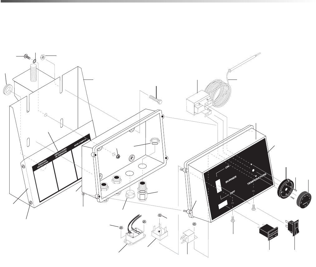
Control Box
Hotsy 1200 8.914-366.0 - R
1
22
4
7
6
21
23
9
13
14
18
19
20
1716
15
12
10
11
8
25
24
26
27
30
31
2
3
5
11
10

39Hotsy 1200 8.914-366.0 - R
Control Box
REF PART NO. QTY DESCRIPTION NOTES
1 8.924-518.0 1 WLMT, CONTROL BOX MOUNT
2 9.803-249.0 4 SCREW, M4 X 10
3 9.802-064.0 1 GROMMET, RUBBER NOZZLE HOLDER
4 8.900-926.0 1 LABEL, HOTSY, 1200 SERIES OPS INSTRUCTIONS
5 8.706-745.0 1 PLUG, PLASTIC
(12V ONLY)
6 9.802-700.0 4 BOLT, 1/4" X 3/4" NC HH
7 9.802-480.0 1 BOX, PLASTIC, BACK
8 9.802-514.0 4 STRAIN RELIEF, STRAIGHT, LQ TITE
(GENERATOR MODELS)
--3 -
(NON-GENERATOR
MODELS)
9 8.750-095.0 1 THERMOSTAT, 2 METER LG CAP, HOTSY
10 9.802-695.0 3 NUT, 10/32" KEPS
11 9.802-530.0 1 RECTIFIER, BRIDGE, MB156
(NON-GENERATOR
MODELS)
- 8.752-804.0 1 REGULATOR, 12 VOLT DC
(1270SS, 1280SS,
1290SS)
12 9.802-471.0 1 RELAY, P&B, VF4A-45-H11 24V/40A
- 9.802-470.0 2 RELAY, 12V
(1270SS, 1280SS,
1290SS)
13 8.719-947.0 1 BOX, PLASTIC FRONT, 2 SQUARE HOLES
14 8.900-924.0 1 LABEL, 1200SSG, CONTROL BOX
15 9.802-771.0 2 SCREW, 10/32" X 3/4" BH SOC CS
--3 -
(GENERATOR MODELS
1270SS,1280SS,
1290SS)
16 9.802-283.0 1 HOUR METER, 120V
17 9.802-451.0 1 SWITCH, ROCKER, CARLING W/GREEN LENS
(GENERATOR MODELS)
- 8.716-036.0 1 SWITCH, ROCKER
(NON-GENERATOR
MODELS)
18 8.712-190.0 1 PLATE, THERMOSTAT PLASTIC COVER
19 8.718-779.0 2 SCREW, 4MM X 6MM, PAN HEAD
20 8.750-097.0 1 KNOB, THERMOSTAT 32-248°
21 9.802-525.0 4 LOCKNUT, 1/2"
(GENERATOR MODELS)
--3 -
(NON-GENERATOR
MODELS)
22 9.802-775.0 4 NUT, 1/4" FLANGE, ZINC
23 8.716-011.0 48”
CONDUIT, FLEXO 1/2" BLACK,
SE50 P-DRO, 500'/RL
24 9.802-762.0 1 SCREW, 10/32" X 1-1/41
25 8.719-012.0 1 WASHER, 10/32" X 1-1/4"1
26 9.802-695.0 4 NUT, 10/32"4
27 9.803-250.0 4 NUT4
28 8.716-206.0 1 FUSE, ATC 30 AMP
(12V ONLY)
NOT SHOWN
29 8.716-223.0 - HOLDER, FUSE
(12V ONLY)
NOT SHOWN
30 8.924-511.0 1 COVER, CONTROL BOX
31 9.802-704.0 4 SCREW, 1/4-20 X 1/2"4

40
Float Tank
Hotsy 1200 8.914-366.0 - R
9
8
7
6
1
5
4
3
11
10
2
11
(NOT USED ON SUPER DUTY OPTION)
12

41Hotsy 1200 8.914-366.0 - R
Float Tank
REF PART NO. QTY DESCRIPTION NOTES
1 8.706-642.0 1 TANK, FLOAT, 4 GALLON W/COVER
2 9.802-754.0 2 SCREW, 1/4" X 1/2"
3 8.749-328.0 1 VALVE, 1/2" PLASTIC FLOAT
4 8.719-648.0 1 ROD, 1/4" X 6" THREADED
5 8.706-512.0 1 BALL, 4.00 DIAMETER PLASTIC FLOAT
6 8.707-020.0 1 BARB, 1/2" MPT X 3/4" BARB
- 8.706-947.0 1 BARB, 1/2" BARB X 1/2" MNPT (1260SS/G ONLY)
7 8.707-061.0 1 STRAINER, 1/2" BASKET
8 9.802-261.0 17" HOSE, 3/4" PUSH-ON
- 9.802-259.0 17" HOSE, 1/2" PUSH-ON (1260SS/G ONLY)
9 9.802-152.0 1 SWIVEL, 3/4" SAE FEMALE, PUSH-ON
- 9.802-151.0 1 SWIVEL, 1/2" JIC FEMALE, PUSH-ON (1260SS/G ONLY)
10 9.802-146.0 1 SWIVEL, 1/2" MP X 3/4" GHF W/STRAINER
11 8.707-000.0 1 CONNECTOR, 1/2" ANCHOR
12 8.706-984.0 1 ADAPTER, 1/2" X 1/2" PIPE (BRASS)

42
Burner Fuel Oil Tank
REF PART NO. QTY DESCRIPTION NOTES
1 9.803-533.0 1 TANK, DIESEL, 11.5 GAL
2 9.803-531.0 1 DIP TUBE ASSY, PLASTIC, 10.75"
3 8.709-069.0 2 CLAMP, SCREW 5/16"W, 1/4-5/8"D, SS
4 9.802-254.0 36" HOSE, 1/4" PUSH-ON, FUEL
5 9.802-053.0 2 BUSHING MOLDED
6 9.803-535.0 1 CAP, FUEL TANK W/GAUGE
7 9.800-002.0 1 LABEL, USE ONLY KEROSENE
8 9.802-054.0 1 ELBOW, 1/4" FUEL TANK, ZINC
1
7
5
2
3
4
6
3
4
8
Inlet to
Burner
Return Line
from Burner
Hotsy 1200 8.914-366.0 - R

43Hotsy 1200 8.914-366.0 - R
Coil Outlet
-
NOTE: Pressure relief safety valve must be inspected and tested by a trained technician annually.
REF PART NO. QTY DESCRIPTION NOTES
1 9.149-003.0 1 DISCHARGE, MANIFOLD COIL OUTLET
2 9.196-012.0 1 SCREW, 10-24 X 1/4" HEX SET
3 8.902-433.0 1 VALVE, SAFETY RELIEF VSA
4 9.802-171.0 1 NIPPLE, PIPE, 3/8" X 3/8" NPT ST MALE
5 8.706-248.0 1 PLUG, 3/8" ALLEN COUNTERSUNK
1
5
3
4
2
1
5
3
4
2

44
Burner
Hotsy 1200 8.914-366.0 - R
To Tank
8
4
13
1
5
19
6
14
18
18
3
7
2
11
9
KNA Burner Gauge
SERVICE HOTLINE 1-800-833-1600
C ELZZON
L
ELECTRODE POSITION
1/8 FOR AC CONE
8.922-740.0
ELECTRODE GAP
1/8 MIN 5/32 MAX
ELECTRODE POSITION
3/16 FOR DC CONE
3/16” FOR
DC CONE
1/8” FOR
AC CONE
1/4” Above
Nozzle Center
Periodically Check Wiring Connections. If Necessary
To Adjust Electrodes, Use Diagram.
Nozzle
Electrode

45Hotsy 1200 8.914-366.0 - R
Burner
REF PART NO. QTY DESCRIPTION NOTES
1 8.918-908.0 1 BURNER, 120V CROSSFIRE
- 8.918-911.0 1 BURNER, 12VDC CROSSFIRE
2 6.390-126.0 2 CLAMP, HOSE, .46 - .54 ST
3 8.754-911.0 1 CHECK VALVE, 1 WAY, 1/4" BARB
4 8.749-771.0 1 FILTER, FUEL/WATER SEPARATOR
- 8.749-770.0 1 ELEMENT, FILTER, HOTSY (REPLACEMENT)
5 8.706-958.0 1 HOSE BARB, 1/4" BARB X 1/4" PIPE, 90°
6 9.802-424.0 5 ft. CORD, 16/4 (115V BURNER)
- 9.802-427.0 5 ft. CORD, 12/3 (12V BURNER)
7 8.706-161.0 1 ELBOW, 1/4" STREET, 90° GALV
8 9.803-264.0 1 NIPPLE, 1/4" X 3", BLACK PIPE
9 8.706-941.0 1 HOSE BARB, 1/4" BARB X 1/4" ML PIPE
10 8.750-781.0 1 CONE, F22 CROSSFIRE
11 8.757-986.0 1
NOZZLE, BURNER, 2.25 90° B CROSSFIRE W/100
PSI CHECK VALVE
12 8.750-778.0 1 ELECTRODE, CROSSFIRE
13 8.700-759.0 1 FUEL PUMP, 120V CROSSFIRE
- 8.700-760.0 1 FUEL PUMP, 12VDC CROSSFIRE
14 8.750-517.0 1 MOTOR, 115V CROSSFIRE
- 8.751-074.0 1 MOTOR.12VDC CROSSFIRE
15 8.919-114.0 1 IGNITOR, 120V CROSSFIRE NOT SHOWN
- 8.919-116.0 1 IGNITOR, 12VDC CROSSFIRE NOT SHOWN
16 8.750-520.0 1 FAN, 120V CROSSFIRE NOT SHOWN
- 8.751-072.0 1 FAN, 12VDC CROSSFIRE NOT SHOWN
17 8.750-520.0 1 COUPLING, 20V CROSSFIRE NOT SHOWN
- 8.751-073.0 1 COUPLING,12VDC CROSSFIRE NOT SHOWN
18 8.709-069.0 2 CLAMP, SCREW, 5/16"W, 1/4-5/8"D SS
19 9.802-519.0 1 STRAIN RELIEF, 1/2” METAL

46
Specifications
Model
Pump Belt
p/n
Pump
Belt
Pump
Pulley p/n
Pump
Pulley
Pump
Bushing p/n
Pump
Bushing
Engine
Pulley p/n
Engine
Pulley
1260SS 9.802-420.0 BX43 8.715-592.0 2BK80 9.802-402.0 H x 24MM 9.802-384.0 2BK34
1260SSG 9.802-420.0 BX43 8.715-593.0 2BK90 9.802-402.0 H x 24MM 9.802-393.0 3TB36
1270SS 8.715-706.0 BX46 8.715-593.0 2BK90 9.802-403.0 H x 25MM 9.802-384.0 2BK40
1270SS/G 8.715-703.0 BX42 8.715-593.0 2BK90 9.802-403.0 H x 25MM 9.802-393.0 3TB36
1280SS 8.715-706.0 BX44 8.715-594.0 2B94SK 8.715-647.0 SK x 25MM 9.802-383.0 2BK36
1280SS/G 9.802-420.0 BX43 8.715-594.0 2B94SK 8.715-647.0 SK x 25MM 9.802-392.0 3TB34
1285SS 8.715-706.0 BX46 8.715-594.0 2B94SK 8.715-647.0 SK x 25MM 9.802-383.0 2BK36
1285SSG 8.715-705.0 BX44 8.715-594.0 2B94SK 8.715-647.0 SK x 25MM 9.802-392.0 3TB34
1290SS 8.715-706.0 BX46 9.802-391.0 2BK100 9.802-403.0 H x 25MM 9.802-383.0 2BK36
1290SS/G 8.715-705.0 BX43 9.802-420.0 2BK100 9.802-403.0 H x 25MM 9.802-392.0 3TB34
Hotsy 1200 8.914-366.0 - R

47Hotsy 1200 8.914-366.0 - R
Specifications
Model
Engine
Bushing p/n
Engine
Bushing
Gen.
Pulley
Generator
Pulley p/n
Generator
Bushing
Generator
Bushing p/n
Generator
Belt p/n
Gen.
Belt
1260SS 9.802-399.0 H x 1 n/a n/a n/a n/a n/a n/a
1260SSG 9.802-404.0 P2 x 1 1B36SH 8.715-578.0 SH x 5/8 8.715-631.0 8.715-671.0 AX28
1270SS 9.802-399.0 H x 1 n/a n/a n/a n/a n/a n/a
1270SS/G 9.802-404.0 P2 x 1 1B36SH 8.715-578.0 SH x 5/8 8.715-631.0 8.715-671.0 AX28
1280SS 9.802-399.0 H x 1 n/a n/a n/a n/a n/a n/a
1280SS/G 9.802-404.0 P2 x 1 AK30 8.715-524.0 H x 5/8 9.802-397.0 8.715-670.0 AX27
1280SS 9.802-399.0 H x 1 n/a n/a n/a n/a n/a n/a
1285SSG 9.802-404.0 P2 x 1 AK30 8.715-524.0 H x 5/8 9.802-397.0 8.715-670.0 AX27
1290SS 9.802-399.0 H x 1 n/a n/a n/a n/a n/a n/a
1290SS/G 9.802-404.0 P2 x 1 AK30 8.715-524.0 H x 5/8 9.802-397.0 8.715-670.0 AX27

48
Pump - 1260SSG
Hotsy 1200 8.914-366.0 - R
19
18
15
16
6
14
13
14
11
17
7
8
7
21
7
14
22
25
12
10
6
5
19
4
3
1
2
23
24
20
17
9

49Hotsy 1200 8.914-366.0 - R
Pump - 1260SSG
REF PART NO. QTY DESCRIPTION NOTES
1 9.802-252.0 24" HOSE, 1/4" X 1/2" BRAIDED VINYL
2 6.390-126.0 1 CLAMP, HOSE, .46 - .54 ST
3 8.706-958.0 1 HOSE BARB, 1/4" BARB X 1/4” PIPE, 90°
4 8.706-915.0 1 BUSHING, 1/2" X 1/4" BRASS
5 8.706-844.0 1 TEE, 1/2" FEMALE, PIPE
6 9.802-129.0 2 ELBOW, 1/2” JIC X 3/8”, 90°
7 9.802-151.0 4 SWIVEL, 1/2" JIC FEMALE, PUSH-ON
8 9.802-259.0 10" HOSE, 1/2" PUSH-ON
9 8.707-212.0 1 VALVE, 1/2" NPT 3-WAY BALL
10 8.706-168.0 1 ELBOW, 3/8" MALE
11 8.933-006.0 1 SWITCH, FLOW, MV60
12 8.750-299.0 1 UNLOADER, VRT3, 8 GPM @ 4500 PSI
13 8.751-180.0 1 PUMP, HOTSY HM4035R
14 9.802-039.0 3 ELBOW, 1/2" JIC X 3/8" MALE
15 8.918-423.0 1 HOSE, 1/2" X 22", 2 WIRE, PRESSURE LOOP
16 9.802-015.0 1 NIPPLE, PIPE, 1/2" X 4" GALV
17 8.706-797.0 2 NIPPLE, 1/2" HEX
18 8.707-232.0 1 VALVE, 1/2" FNWTSC12, BRASS, SWING CHECK
19 9.802-131.0 2 ELBOW, 1/2" JIC, 1/2"
20 9.802-259.0 16" HOSE, 1/2" PUSH-ON
21 9.802-126.0 1 PLUG, 1/2" JIC
22 8.911-830.0 1 RAIL, PUMP SLIDER
23 9.802-807.0 4 WASHER
24 9.802-744.0 4 BOLT
25 8.707-254.0 1 PUMP PROTECTOR, 3/8" 145°

50
Pump - 1270SSG, 1280SSG, 1285SSG, 1290SSG
21
20
15
19
18
11
17
16
28
14
13
9
7
8
7
26
7
14
23
27
12
10
11
5
6
4
3
1
2
22
25
24
Hotsy 1200 8.914-366.0 - R

51Hotsy 1200 8.914-366.0 - R
Pump - 1270SSG, 1280SSG, 1285SSG, 1290SSG
REF PART NO. QTY DESCRIPTION NOTES
1 9.802-252.0 24" HOSE, 1/4" X 1/2" BRAIDED VINYL
2 6.390-126.0 1 CLAMP, HOSE, .46 - .54 ST
3 8.706-958.0 1 HOSE BARB, 1/4" BARB X 1/4" PIPE, 90°
4 8.706-915.0 1 BUSHING, 1/2" X 1/4" BRASS
5 8.706-844.0 1 TEE, 1/2" FEMALE, PIPE
6 9.802-131.0 1 ELBOW, 1/2" JIC X 1/2", 90°
7 9.802-151.0 4 SWIVEL, 1/2" JIC FEMALE, PUSH-ON
8 9.802-259.0 10" HOSE, 1/2" PUSH-ON
9 8.706-881.0 1 NIPPLE, 3/4" PIPE X 1/2" PIPE
10 8.706-168.0 1 ELBOW, 3/8" MALE
11 9.802-129.0 2 ELBOW, 1/2" JIC X 3/8", 90°
12 8.750-299.0 1 UNLOADER, VRT3, 8 GPM @ 4500 PSI
13 8.933-006.0 1 SWITCH, FLOW, MV60
14 9.802-039.0 2 ELBOW, 1/2" JIC X 3/8" MALE
15 8.918-423.0 1 HOSE, 1/2" X 22", 2 WIRE, PRESSURE LOOP
16 9.802-040.0 1 ELBOW, 1/2" JIC, 1/2", 90°STL
17 8.706-800.0 1 NIPPLE, 3/4" HEX
18 8.707-235.0 1 VALVE, 3/4" BRASS, SWING CHECK
19 8.706-799.0 1 NIPPLE, PIPE, 3/4" X CLOSE
20 9.803-558.0 1 VALVE, 3/4" BALL BRASS, 3-WAY
21 9.803-557.0 1 ELBOW, 3/4" SAE X 3/4", 90°
22 9.802-807.0 4 WASHER
23 8.911-830.0 1 RAIL, PUMP SLIDER
24 9.802-259.0 16" HOSE, 1/2" PUSH-ON
25 9.802-744.0 4 BOLT
26 9.802-126.0 1 PLUG, 1/2" JIC
27 8.707-254.0 1 PUMP PROTECTOR, 3/8" 145°
28 8.920-584.0 1 PUMP, HX8043R (1280SS/G, 1290SS/G)
- 8.920-583.0 1 PUMP, HX5843R.2 (1270SS/G)

52
Pump Super Duty "Option" - 1285SSG
Hotsy 1200 8.914-366.0 - R
1
2
3
4
16
4
15
13
12
14
11
10
7
5
1
8
9
28
17
18
16
4
4
19
20
21
22
23
25
24
26
6
27

53Hotsy 1200 8.914-366.0 - R
Pump Super Duty "Option" - 1285SSG
REF PART NO. QTY DESCRIPTION NOTES
1 9.802-040.0 2 ELBOW, 1/2" JIC, 1/2", 90°
2 8.715-459.0 1 UNLOADER, PA 21 GPM @4350 PSI VB 80/280
3 9.802-131.0 1 ELBOW, 1/2" JIC X 1/2", 90°
4 9.802-151.0 4 SWIVEL, 1/2" JIC FEMALE, PUSH-ON
5 8.704-196.0 1 SWITCH, PRESSURE HP, RED 5800 PSI
6 8.706-925.0 1 BUSHING 3/4" X 1/2" PIPE
7 8.706-236.0 1 TEE, 1/2", STREET
8 8.706-838.0 1 ELBOW, 1/2" STREET, 45°
9 9.802-146.0 1 SWIVEL, 1/2" MP X 3/4" GHF W/STRAINER
10 8.706-315.0 1 SWIVEL, 1/2" JIC, 1/2" MALE
11 9.802-037.0 1 NIPPLE, 1/2" JIC, 3/8" FEMALE
12 8.706-958.0 1 HOSE BARB, 1/4" BARB X 1/4" PIPE, 90°
13 8.706-915.0 1 BUSHING, 1/2" X 1/4" BRASS
14 8.706-881.0 1 NIPPLE, 3/4 PIPE X 1/2 PIPE
15 8.706-844.0 1 TEE, 1/2" FEMALE, PIPE
16 9.802-129.0 2 ELBOW, 1/2" JIC X 3/8", 90°
17 8.918-422.0 1 HOSE, 3/8" X 20", 2-WIRE
18 8.920-584.0 1 PUMP HX8043R
19 9.802-259.0 16" HOSE, 1/2" PUSH-ON
20 9.802-126.0 1 PLUG, 1/2, JIC
21 8.911-830.0 1 PUMP SLIDER
22 9.802-807.0 4 WASHER, 3/8, SAE, FLAT
23 9.802-744.0 4 BOLT, 10MM X 20MM, HH
24 9.802-252.0 10" HOSE, 1/4" X 1/2", BRAIDED VINYL
25 6.390-126.0 1 CLAMP, HOSE
26 9.802-259.0 7" HOSE, 1/2" PUSH-ON
27 8.706-294.0 1 BUSHING, 1/2" X 3/8"
28 9.802-040.0 1 ELBOW, 1/2" JIC X 1/2" MPT

54
Hose, Gun, & Wand
REF PART NO. QTY DESCRIPTION NOTES
1 8.739-054.0 1 HOSE, 3/8" X 50', 2 WIRE, TUFF SKIN
2 8.725-388.0 1 WAND, SINGLE, 48" INSULATED W/SIDE GRIP
3 9.802-164.0 2 COUPLER, 1/4" FEMALE, BRASS
4 8.751-235.0 1 GUN, HOTSY, H1050, 5000 PSI, 10.4 GPM
5 8.707-139.0 1 NIPPLE, 1/4" X 1/4" NPT ST MALE
6 9.802-166.0 1 COUPLER, 3/8" FEMALE
- 9.802-100.0 1 O-RING REPLACEMENT
7 8.712-353.0 1 NOZZLE, SAQCMEG 0005, RED (1260SS/G)
- 8.712-354.0 1 NOZZLE, SAQCMEG 1505, YELLOW (1260SS/G)
- 8.712-356.0 1 NOZZLE, SAQCMEG 4005, WHITE (1260SS/G)
- 8.712-349.0 1 NOZZLE, SAQCMEG 004.5, RED (1270SS/G)
- 8.712-350.0 1 NOZZLE, SAQCMEG 1504.5, YELLOW (1270SS/G)
- 8.712-352.0 1 NOZZLE, SAQCMEG 4004.5, WHITE (1270SS/G)
- 8.712-357.0 1 NOZZLE, SAQCMEG 005.5 RED (1280SS/G)
- 8.712-358.0 1 NOZZLE, SAQCMEG 1505.5, YELLOW (1280SS/G)
- 8.712-360.0 1 NOZZLE, SAQCMEG 4005.5, WHITE (1280SS/G)
- 8.712-365.0 1 NOZZLE, SAQCMEG 006.5, RED (1290SS/G)
- 8.712-366.0 1 NOZZLE, SAQCMEG 1506.5, YELLOW (1290SS/G)
- 8.712-368.0 1 NOZZLE, SAQCMEG 4006.5, WHITE (1290SS/G)
Hotsy 1200 8.914-366.0 - R
6
1
5
4
3
2
3
7

55Hotsy 1200 8.914-366.0 - R
HX. 2 Pump Series
REF PART NO. QTY DESCRIPTION NOTES
1 8.752-825.0 1 CRANKCASE
2 - 3 PLUNGER OIL SEAL SEE KITS TABLE
3 - 3 O-RING Ø1.78 X 37.82 SEE KITS TABLE
4 - 3 PRESSURE RING SEE KITS TABLE
5 - 3 U-SEAL SEE KITS TABLE
6 - 3 INTERMEDIATE RING SEE KITS TABLE
7 - 3 U-SEAL SEE KITS TABLE
8 9.803-285.0 1 BRASS PLUG, G3/4
9 9.803-286.0 1 COPPER WASHER 3/4
10 8.752-831.0 1 MANIFOLD HOUSING Ø22/Ø20/
11 8.752-836.0 6 O-RING Ø2.62 X 21.89
12 - 6 VALVE ASSEMBLY SEE KITS TABLE
13 9.803-287.0 6 O-RING Ø3.53 X 25.80-134
14 8.752-855.0 6 VALVE PLUG
15 8.752-833.0 8 MANIFOLD STUD BOLT
16 9.802-890.0 8 LOCK WASHER
17 9.803-199.0 1 COPPER WASHER 1/2
TORQUE SPECS
ITEM # FT. LBS.
14 95
15 45
23 8
3410
42 30
48 8
5
7
12
12
Pompe XLT serie 2011
HAWK
XLT3020S
XLT3816S
XLT1830
XLT2230
XLT2530
XLT2520
XLT2730
XLT3025
XLT3020
XLT3325
XLT3517
XLT4017
XLT4014
XLT4317
XLT5015
XLT5415
23
24
25
26
27
28
29
30
27
31
26
32
33
24
23
34
35
36
37
38
39
40
41
42
43
44
45
46
47
48
2
3
4
6
8
9
10
13
14
15
16
17
18
19
20
21
22
13
14
11
11
1

56
HX. 2 Pump Series
REF PART NO. QTY DESCRIPTION NOTES
18 9.802-926.0 1 BRASS PLUG 1/2
19 - 6 VALVE SEAT SEE KITS TABLE
20 - 6 VALVE PLATE SEE KITS TABLE
21 - 6 VALVE SPRING SEE KITS TABLE
22 - 6 VALVE CAGE SEE KITS TABLE
23 8.752-830.0 8 HEX SCREW
24 9.802-884.0 8 WASHER
25 9.803-182.0 1 CLOSED BEARING HOUSING
26 9.803-186.0 2 O-RING Ø2.62 X 71.12
27 9.803-160.0 2 ROLLER BEARING
28 8.752-828.0 1 CRANKSHAFT Ø25 (5843)
- 8.752-829.0 1 CRANKSHAFT Ø25 (80439536)
- 8.752-827.0 1 CRANKSHAFT Ø25 (1036)
29 9.803-293.0 1 CRANKSHAFT KEY
30 8.752-834.0 1 OIL DIP STICK
31 9.803-139.0 1 CRANKSHAFT SEAL
32 9.803-177.0 2 SHIM
33 9.803-181.0 1 BEARING HOUSING
34 8.752-841.0 3 PLUNGER BOLT
35 8.752-820.0 3 BONDED SEAL
36 8.752-846.0 3 PLUNGER, 20MM (5843,8043)
- 8.752-847.0 3 PLUNGER, 22MM (9536,1036)
37 8.752-823.0 3 COPPER SPACER
38 8.752-842.0 3 PLUNGER ROD
39 8.752-822.0 3 CONNECTING ROD PIN
40 8.752-821.0 3 CONNECTING ROD
41 9.802-889.0 6 SPRING WASHER
42 9.802-937.0 6 CONNECTING ROD SCREW
43 9.803-194.0 1 O-RING Ø2.62 X 152.07
44 8.752-826.0 1 CRANKCASE COVER
45 9.803-906.0 1 O-RING Ø1.78 X 14.00
46 8.707-262.0 1 BRASS PLUG G3/8
47 9.803-202.0 1 SIGHT GLASS G3/4
48 8.752-824.0 5 COVER SCREW
Hotsy 1200 8.914-366.0 - R

57Hotsy 1200 8.914-366.0 - R
HX. 2 Pump Series
KIT NUMBERS
8.752-843.0 8.752-844.0 8.752-849.0 8.752-850.0 8.752-838.0 8.752-839.0
KIT
DESCRIPTION
Plunger
Seal
20 mm
(5843, 8043)
Plunger
Seal
22 mm
(9536,1036)
Seal
Packing
20 mm
(5843, 8043)
Seal
Packing
22 mm
(9536,1036)
Plunger
20 mm
(5843, 8043)
Plunger
22 mm
(9536,1036)
ITEMS NUMBERS
INCLUDED
3, 5, 7 3, 5, 7 3, 4, 5, 6, 7 3, 4, 5, 6, 7 34, 35, 36, 37 34, 35, 36, 37
NUMBER OF
CYLINDERS KIT
WILL SERVICE
331111
KIT NUMBERS 8.753-349.0 8.752-835.0
KIT
DESCRIPTION
Complete Valve
Plunger Oil
Seal
ITEMS
NUMBERS
INCLUDED
11, 12, 13 2
NUMBER OF
CYLINDERS KIT
WILL SERVICE
66

58
HM.3 Series Pump
REF PART NO. QTY DESCRIPTION NOTES
1 8.751-216.0 1 CRANKCASE
2 - 3 PLUNGER OIL SEAL SEE KITS TABLE
3 - 3 O-RING Ø1.78 X 31.47 SEE KITS TABLE
4 - 3 PRESSURE RING SEE KITS TABLE
5 - 3 U-SEAL SEE KITS TABLE
6 - 3 INTERMEDIATE RING SEE KITS TABLE
7 - 3 U-SEAL SEE KITS TABLE
8 9.803-199.0 1 WASHER, COPPER
9 9.802-926.0 1 PLUG, BRASS 1/2
10 8.751-218.0 1 MANIFOLD HEAD
11 - 6 O-RING Ø2.62 X 17.13 SEE KITS TABLE
12 - 6 VALVE ASSEMBLY SEE KITS TABLE
13 - 6 O-RING Ø2.62 X 20.29 SEE KITS TABLE
14 9.802-928.0 6 VALVE PLUG
15 9.802-938.0 8 MANIFOLD STUD BOLT
16 9.802-884.0 16 WASHER
17 9.803-198.0 1 COPPER WASHER 3/8
18 9.802-925.0 2 BRASS PLUG 3/8
23 9.802-944.0 8 HEXAGONAL SCREW
24 8.717-210.0 1 CLOSED BEARING HOUSING
25 9.803-192.0 2 O-RING Ø1.78 X 60.05
26 8.933-011.0 2 TAPERED ROLLER BEARING
27 8.751-222.0 1 CRANKSHAFT (3540)
Hotsy 1200 8.914-366.0 - R
34
33
30
31
32
16
23
35
36
37
38
39
40
41
42
43
44
45
46
48
47
18
TORQUE
SPECS
Item # Ft.-lbs
14 75
15 30
23 8
33 9
43 13
48 7.6
23
24
25
25
26
26
1
2
4
5
3
6
8
9
10
11
12
13
14
15
16
18
17
7
27
28
29
16

59Hotsy 1200 8.914-366.0 - R
HM.3 Series Pump
REF PART NO. QTY DESCRIPTION NOTES
- 8.751-223.0 1 CRANKSHAFT (4030, 4035)
- 8.717-063.0 1 CRANKSHAFT (4031)
28 9.803-167.0 1 CRANKSHAFT KEY
29 9.802-921.0 1 OIL DIP STICK
30 9.803-140.0 1 CRANKSHAFT SEAL
31 9.803-178.0 2 SHIM
32 8.717-209.0 1 BEARING HOUSING
33 - 3 PLUNGER NUT, M8 SEE KITS TABLE
34 - 3 COPPER SPACER SEE KITS TABLE
35 - 3 PLUNGER SEE KITS TABLE
36 - 3 COPPER SPACER SEE KITS TABLE
37 - 3 O-RING SEE KITS TABLE
38 - 3 TEFLON RING SEE KITS TABLE
39 8.751-224.0 3 PLUNGER ROD (4030, 4031, 4035)
- 8.751-225.0 3 PLUNGER ROD (3540)
40 9.803-158.0 3 CONNECTING ROD
41 8.751-228.0 3 CONNECTING ROD PIN
42 9.803-218.0 6 SPRING WASHER
43 9.803-238.0 6 CONNECTING ROD SCREW
44 70-060009 1 O-RING, Ø2.62 X 126.67
45 8.751-229.0 1 CRANKCASE COVER
46 9.803-197.0 1 O-RING, Ø1.78 X 14
47 9.803-202.0 1 SIGHT GLASS 3/4
48 9.802-939.0 5 COVER SCREW
REPAIR KIT NO. 8.725-360.0 8.725-362.0 8.725-358.0 8.725-361.0 8.725-363.0 8.725-359.0
KIT
DESCRIPTION
Plunger
Seal
4035
18mm
Plunger
Seal 4030, 4031
20mm
Plunger
Seal
3540
15mm
Complete Seal
Packing
4035
18mm
Complete Seal
Packing
4030, 4031
20mm
Complete Seal
Packing
3540
15mm
ITEMS NUMBERS
INCLUDED
3, 5, 7 3, 5, 7 3, 5, 7 3, 4, 5, 6, 7 3, 4, 5, 6, 7 3, 4, 5, 6, 7
NO. OF CYLINDERS
KIT WILL SERVICE
33311 1
REPAIR KIT NO. 8.751-237.0 8.751-238.0 8.933-023.0 8.752-835.0 8.753-349.0
KIT
DESCRIPTION
Plunger
4035
18mm
Plunger
4030,
4031
20mm
Plunger
354015mm
Plunger Oil Seal Complete Valve
ITEMS NUMBERS
INCLUDED
33, 34, 35, 36,
37, 38
33, 34, 35, 36,
37, 38
33, 34, 35,36,
37, 38
2 11, 12, 13
NO. OF CYLINDERS
KIT WILL SERVICE
11136

60
VRT3 Unloader
REF PART NO. QTY DESCRIPTION NOTES
25 8.750-713.0 1 OUTLET FITTING
18 8.750-712.0 1 KNOB, UNLOADER
- 8.750-709.0 - REPAIR KIT, VRT3, 2320/3630 PSI
- 8.750-710.0 - REPAIR KIT, VRT3, 4500 PSI
- - - (KIT ITEMS: 3, 4, 6, 9-12, 21, 24)
Hotsy 1200 8.914-366.0 - R
8.750-297.0, 8 GPM, 2320 PSI
8.750-298.0, 8 GPM, 3630 PSI
8.750-299.0, 8 GPM, 4500 PSI
9
8
23
26
2
3
16
1
10
24
11
6
4
13
14
20
25
12
22
19
15
15
21
17
18
7
9
5
6

61Hotsy 1200 8.914-366.0 - R
VRT3 Unloader
Unloader Adjustment Procedures
1. Remove lock nut (Item 19).
2. Remove adjustment knob (Item 18).
3. Loosen the two (2) nuts (Item 15), move them upward on stem (Item 8) until you see 4 or more threads below
the nut.
4. Re-attach adjusting knob (Item 18).
5. Start machine. Open the trigger of the spray gun. Increase pressure by turning adjustment knob (Item 18)
clockwise until pressure is at the desired operating pressure.
6. Remove the adjustment knob (Item 18), tighten the lower nut (Item 15) tightly against the upper nut (Item 15).
Re-attach adjustment knob (Item 18) and screw down until contact is made with the nuts (Items 15). Screw
down lock nut (Item 19) onto the stem (Item 8) until the threads cut into the nylon insert of the lock nut
(Item19).
*If adjustment knob (Item 18) DOES NOT make contact with upper nut (Items 15), remove adjusting knob (Item
18), re-adjust (raise) nuts (Items 15) on stem (Item 8) and re-attach adjustment knob (Item 18), then repeat
step #6.
**If adjustment knob (Item 18) DOES make contact with upper nut; release the trigger of the spray gun and
watch the pressure gauge for the pressure increase (“spike”). This “spike” SHOULD NOT exceed 500 psi
above the operating pressure. If “spike” pressure exceeds the 500 psi limit, remove the adjusting knob (Item
18) and re-adjust (lower) the nuts (Items 15) on the stem (Item 8). Re-attach the adjusting knob (Item 18), then
repeat step #6.

62
Crossfire Burner
For best performance specify Crossfire replacements parts
Hotsy 1200 8.914-366.0 - R
28
36
36
1
1
31
36
47
30
16
15
22
33
33
40
17
14
3
27
5
5
48
45
49
29
46
39
39
7
7
8
9
2
38
32
36
4
44
6
36
36
12
11
13
3
39
39
23
21
20
18
19
10
35
34
43
37
37
37
25
24
41
26

63Hotsy 1200 8.914-366.0 - R
Crossfire Burner
REF PART NO. QTY DESCRIPTION NOTES
1 8.919-050.0 1 BURNER HOUSING ASSEMBLY
2 8.751-160.0 1 AIR GUIDE
3 8.754-705.0 1 FUEL PUMP, SUNTEC OL35 12-24 V SOL
- 8.700-759.0 1 FUEL PUMP, SUNTEC A2VA-3106 120 V SOL
- 8.700-760.0 1 FUEL PUMP, SUNTEC A2VA-3106 230 V SOL
4 9.807-348.0 1 LABEL, CLEAR MYLAR
5 9.802-510.0 2 CABLE, TIE, 4” BLACK
6 8.750-541.0 1 AIR BAND
7 8.750-517.0 1 MOTOR,1/6 HP 115V 60HZ
- 8.750-518.0 1 MOTOR,1/6 HP 230V 60HZ
- 8.750-074.0 1 MOTOR,1/7 HP 12VDC AMETEK
8 8.750-543.0 1 COUPLING, FLEX, 1/2” X 5/16”
- 8.751-073.0 1 COUPLING, FLEX, 5/16” X 5/16”
9 8.750-520.0 1 FAN, 4.53” X 2.42”,1/2” BORE, F115-62S
- 8.751-072.0 1 FAN, 4.53” X 2.42”, .313 BORE, F115-625
10 8.900-083.0 1 100 PSI SNAP CHECK VALVE
11 8.750-547.0 1 CONNECTOR, 37° FLARE X 1/8” NPT, LONG
12 8.750-545.0 1 CONNECTOR, 37° FLARE X 1/8” NPT
13 8.749-000.0 1 FUEL LINE ASSEMBLY
14 8.752-034.0 1 FLANGE, KNA BURNER, 1” TUBE
15 8.752-035.0 1 FLANGE, KNA BURNER, 3” TUBE
16 8.750-539.0 1 GASKET, FLANGE
17 8.751-354.0 1 GASKET, BURNER TUBE
18 8.750-526.0 1 GUN, ELECTRODE/NOZZLE, 3”
19 8.750-525.0 1 GUN, ELECTRODE/NOZZLE, 1”
20 9.802-577.0 1 FUEL NOZZLE 2.25 X 90 B
21 8.750-778.0 1 ELECTRODE, IGNITION, AC
- 8.751-342.0 1 ELECTRODE, IGNITION, DC
22 8.750-779.0 1 CONE, AIR F4
- 8.750-782.0 1 CONE, AIR F6
- 8.750-780.0 1 CONE, AIR F12
- 8.750-781.0 1 CONE, AIR F22
23 8-919-114.0 1 IGNITER, BURNER 120V
- 8-919-115.0 1 IGNITER, BURNER 230V
- 8-919-116.0 1 IGNITER, BURNER 12VDC
24 8.751-165.0 1 PLUG, HOLE 0.875 PLASTIC
25 8.754-905.0 1 GASKET, KNA BURNER PUMP SUNTEC
26 8.751-134.0 1 PLUG, 1/8” NPT X HEX SHOULDER
27 8.918-454.0 1 GASKET, JUNCTION BOX
28 8.750-542.0 1 COVER, JUNCTION BOX
29 8.750-116.0 1 BLOCK, TERMINAL, 5 POLE

64
Crossfire Burner
REF PART NO. QTY DESCRIPTION NOTES
30 8.750-817.0 2 LIGHT, INDICATOR, GREEN,14V
- 8.750-818.0 1 LIGHT, INDICATOR, GREEN, 28V
- 8.750-819.0 1 LIGHT, INDICATOR, GREEN, 125V
- 8.750-820.0 1 LIGHT, INDICATOR, GREEN, 250V
31 8.750-784.0 1 SITE GLASS
32 8.750-785.0 1 RING, PUSH ON INTERNAL, 1305-112
33 8.733-001.0 2 SCREW, 8 X 1/4” HI LOW THREAD CUT PPH
34 8.718-762.0 2 SCREW, 8-32 X 1/2”,M PH RDH PL
35 9.807-345.0 1 LABEL, IGNITER 120V
- 9.807-346.0 1 LABEL, IGNITER 230V
- 9.807-347.0 1 LABEL, IGNITER 12VDC
36 8.718-810.0 6 SCREW, 10/32 X 1/2”, WHIZ LOC FLANGE
37 8.750-770.0 3 SCREW, 10/32 X 5/8’, WHIZ LOC FLANGE
38 8.750-816.0 1 SCREW, 10/32 X 1/4”, GROUNDING
39 8.750-768.0 4 SCREW, 1/4-20 X 1”, PHIL FHMS
40 8.750-771.0 4 SCREW, 1/4-20 X 1/2”, WHIZ LOC FLANGE
41 9.802-745.0 1 SCREW, 10/32 X 1/2” SHCS
42 - 1 LABEL, BRAND NAME NOT SHOWN
43 9.801-268.0 1 LABEL, DISCONNECT POWER SUPPLY
44 - LABEL, SERIAL PLATE1
45 8.750-830.0 1 PLUG, HOLE 0.285 PLASTIC
46 9.807-339.0 1 LABEL, WIRING DIAGRAM, BURNER 115V-115V
- 9.807-340.0 1 LABEL, WIRING DIAGRAM, BURNER 230V-230V
- 9.807-341.0 1 LABEL, WIRING DIAGRAM, BURNER 230V-115V
- 9.807-342.0 1 LABEL, WIRING DIAGRAM, BURNER 115V-24V
- 9.807-343.0 1 LABEL, WIRING DIAGRAM, BURNER 230V-24V
- 9.807-344.0 1 LABEL, WIRING DIAGRAM, BURNER 12VDC
47 9.801-274.0 1 LABEL, BURNER LIGHTS
48 8.919-105.0 1 PLATE, TERMINAL BLOCK NUMBERS
49 8.716-451.0 1 TERMINAL, JUMPER SPADE
Hotsy 1200 8.914-366.0 - R

65Hotsy 1200 8.914-366.0 - R
Wiring Diagram - 1260SS, 1280SS

66
Wiring Diagram - 1270SS, 1280SS, 1290SS
Hotsy 1200 8.914-366.0 - R

67Hotsy 1200 8.914-366.0 - R
Wiring Diagram - 1260SSG, 1285SSG

68
Wiring Diagram - 1270SSG, 1280SSG, 1290SSG
Hotsy 1200 8.914-366.0 - R

69Hotsy 1200 8.914-366.0 - R
Wire Routing Diagram
Battery
Box
Battery
Cables
Generator
Power Cord
Generator

8.914-366.0 • Printed in U.S.A.
If you need SERVICE on your pressure washer, contact your local Hotsy
dealer or visit www.Hotsy.com. Smart phone users scan the code below to
link directly to the Service Request page.
T
o REGISTER your pressure washer, please visit our W
arranty Registration
page at www.hotsy.com/WarrantyRegistration.aspx or scan the code
below with your smart phone.
