
First – a few words of advice and caution:
1. Please do this job with two people. Attempting to do it alone, though heroic, could lead to
product damage or injury because some things can be too heavy for just one person to safely
handle. With two people, the job will be much smoother and safer.
2. Please read and follow the instructions carefully, as it will save time and avoid possible
incorrect installation of the product.
3. Please do not over-tighten screws and bolts, as it may lead to “stripping” the threads and
make the connection weak. The best rule of thumb is “snug is good”.
4. If you will be installing your Murphy Bed on a hard surface such as stone, hardwood floor, tile,
(not carpet), please lay down sufficient padding (such as blankets, comforters, etc.) to protect
the wood parts of your wallbed from the floor, and vice-versa.
5. Before you begin your installation, PLEASE take a few minutes to WATCH our helpful assembly
VIDEO which is available for viewing online at www.wallbedgallery.com/video
WALLBED
Assembly Instructions
Congratulations and a Big Thank You for your purchase of a Wallbed Gallery Murphy Bed!
We sincerely appreciate your business!
1

PREPARATION FOR ASSEMBLY:
Please locate and confirm that you have the following 5 boxes.
WALLBED – BOX LIST – Queen Size
BOX # SKU# DESCRIPTION
1 **43()-H Horizontal Case Panels and Spring Cover
2 **43()-S Vertical Case Panels
3 A143-BH Iron Spring Base Wall Frame and H Mount Frame
4 **43F()-TL Wallbed Left Euroslat Tray
5 **43F()-TR Wallbed Right Euroslat Tray
A. Please locate the “Hardware Parts List” included with these instructions.
B. Please carefully open and un-pack box #1.
a. Inside you will find 3 horizontal panel parts and Bubble Pack #1 – which has tools and connectors.
b. Please carefully sift through the debris field of each carton you open to make sure no hardware parts
came loose in shipping.
C. TOOLS YOU NEED TO SUPPLY:
a. A power drill gun with a #2 Phillips-head drive is required.
b. A flat-head screw driver is required.
c. A pair of pliers will be very helpful.
D. Please be aware that further hardware parts will appear in other boxes as the Assembly Project progresses.
EXAMPLE BOXES
2

STEP 1: SETTING UP THE BED CASE
FROM BUBBLE PACK #1, FOUND IN BOX #1, Please use the 11 bolts and barrel nuts, along with the #5 Allen Wrench and/or #5 Allen Head for Power
Drill (the larger ones) to assemble the Bed Case as shown below.
1A – Lay out the parts from boxes 1 and 2as shown. YOU ARE BUILDING THE BED CASE FACE-DOWN. The notches in the back of the side panels
must be toward the wall where the bed will go, and 20 inches away from the wall.
ASSEMBLY SEQUENCE
Using the bolts & barrel
nuts:
Begin by attaching the
top panel with the top
crown molding facing
down to the floor as
shown.
Next – attach the small
“top-back” panel as
shown.
Last – attach the larger
back panel in the
center. PLEASE NOTE:
There is a groove in this
panel – Please orient
this panel so that the
groove is toward the top
of the wallbed and NOT
toward the wall.(It will
look nicer that way.)
3
HELPFUL HINT: Remember – if
you are installing on a hard
tile/stone/wood floor, be sure
to lay down some blankets to
avoid damage.
Use Dowels to
guide panels
into position.
WALL
Side panel notch
WALL
Dowel
s
bolt-into-barrel nut
back
attach third
top back
attach second
top
attach
first
Wall 20
inch
away
spring cover panel-
Please set spring cover panel
aside. We will use it later.

1B– Stand the assembled Bed Case up and move to the desired position against the wall. Use screws to install the door stops from
Bubble #1 on bed case side panels.
4
OPERATION SEQUENCE
(Before you do this – check AGAIN that
there is at least 20 inches from the wall to
the side panels.)
Begin with TWO PEOPLE standing at the top
corners of the bed case.
Next – Each person grasps the top crown
molding with one hand.
Next – LIFTING WITH YOUR LEGS – NOT YOUR
BACK – stand the bed case up.
Next – Grasping the side panel on each
side, carefully lift and adjust the bed case
back to the wall.
Last – Measure space on either side for
Bookcases (if purchased). Stand back and
assure that you like how the wallbed looks
there. Gently lift and make adjustments as
needed.
BE SURE – Take your time, because you’re
not going to want to move it again once it
is fully installed.
Electrical
outlet
BRACKET
SIDE
PANEL

STEP 2: SETTING UP AND INSTALLING THE SPRING BASE
The best results will be achieved by following these instructions carefully.
TOOLS YOU WILL NEED TO SUPPLY:
1. A power drill gun with a #2 Phillips head,
2. A tape measure or ruler.
STEP 2A – Please measure the thickness of your base molding as shown on the figure here:
Please write this English Fraction or Millimeter measurement here____________, we will use this number in a few minutes.
STEP 2B - In box # 3, please collect the spring carriage frame, the left and right flange arms, the two spacer-brackets,
(and if you have no baseboard, you will also need the two flange spacer blocks.)
From bubble pack #2, please take out the 4 wing bolts.
WALL
FLOOR
base molding
thickness of base molding
MEASURE THICKNESS
OF BASE MOLDING
5
Helpful Hint:
If you are installing on
a hard floor – you may
have a small half-inch
round molding at the
bottom of your
baseboard. This
smaller molding will
have to be cut and
removed where the left
and right flanges will
touch flush against the
baseboard.
Flange
spacer
block
2 pieces
Wing Bolt
4 pieces

STEP 2C – You will notice that the left and right flange arms can be attached to the spring carriage in two positions
– and this is where the base-board thickness measurement comes in:
OPTIONS:
1. If you have no base board or ¼” baseboard – you will use the pre-drilled wood Flange Spacer Blocks – and you will use the “extended”
position.
2. If your base board is 1/4” to 3/8 inch – you will use the “extended” position without the Flange Spacer Block.
3. If your base board is more than 1/2 inch – you will use the “tight” position.
Helpful Hint:
DO NOT use the Wing bolts yet
– this page is ONLY about
figuring out the correct way to
configure the Spring Base!
6
This is the correct Technique
when you have:
1. No baseboard
2. A thin plastic coped runner
3. A carpet toe-kick
4. A wooden baseboard less than 3/8” thick.
Extended
Position
Use the Extended Position and the
spacer block when your base board is
between Zero(none) and 1/4” thick.
Extended
Position
Tight
Position

STEP 2D – Connect Flange arms to the Spring Carriage Frame using the four Wing Bolts, and
Carefully place the Spring Carriage Frame into the bed case (don’t scratch the wood)
STEP 2E- Install the assembled Spring Base into the “Base Plate” at floor level inside your wall.
First – A word about the “Base Plate”.
Most everybody knows what a “two-by-four” is; it’s a piece of wood that is about 1.5” thick and 3.5”wide, and usually quite long unless cut.
But, unless a person has worked in the construction trades, or seen homes under construction, one would not often know that there is a 2x4 lying
flat on the floor inside your walls.
This is the “base plate” that is supporting all the vertical 2x4’s that are behind the drywall or plaster in your walls. This base plate is nailed
into the floor, and with all the vertical 2/4’s on top of it – which end up carrying the weight of the roof – the base plate has the entire weight of the
house resting on it.
We are going to hang your wallbed on the base plate – which is a very, very stable and virtually immovable part of your house.
WALL
FLOOR
base molding
DRYWALL
5
8
"
FOOTER STUD
INSIDE THE
WALL
7
Carefully set the spring
base into the Bed Case
without scratching the
wood.
Base Plate
inside the wall
top plate
Wall stud
Electric plug
socket
“Bottom plate”, “Base plate”, “sole
plate”, are all names for this 2x4
that runs across the floor at the
bottom of a wall.
Side panel
of bed case
Wing bolt
Flange arm
Spring carriage

STEP 2F– Use the Anchor Screws in bubble pack #2 to connect Flange Arms to the Base Plate.
WALL
base molding
FOOTER STUD
INSIDE THE
WALL
DRIVE SCREWS
A 10 DEGREE
DOWN-ANGLE
Base Plate
inside the wall
8
IF YOUR BASE MOLDING IS SOLID WOOD …..
PLEASE USE A 1/8” DRILL BIT TO PRE-DRILL
THROUGH THE BASE MOLDING ONLY (NOT
BASE PLATE) TO REDUCE THE CHANCE OF
SPLITTING YOUR BEAUTIFUL WOOD MOLDING
DRIVER SCREWS AT
A 10 DEGREE
DOWN-ANGEL
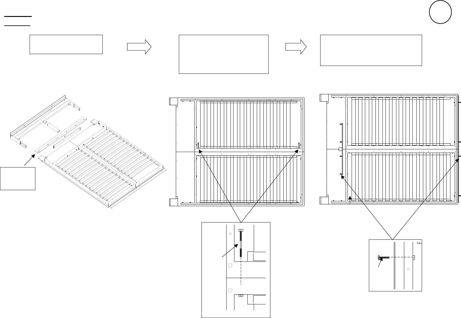
STEP 3 – Building the Bed Frame
STEP 3A – Install metal frame from boxes3,4, and5,and connect them with the connection hardware in bubble #3.
Long
bolt
Left
frame
right
frame
○
3 Using short bolt connect
metal plate and T tube
9
○
1 lay metal as shown
○
2 using long bolt connect
left/right tray frame at the
top and bottom of the tray
Short
bolt
Wooden
Tray Skirt

○
4 Using screws, connect the wooden tray skirt
Short bolt
○
5 Install H-FRAME using short bolts to connect it
Screw
10
Wooden
Tray Skirt
Wooden
Tray Skirt
Install the Wooden Tray Skirt on the
back side of the Bed Tray Panels

STEP 3B – Install the 2-piece flat deck from boxes 4&5 and attach the mattress hoop and flip-over feet from box 3 to the
bed tray as shown here, and connect them with the connection hardware in bubble pack #3. Using the wrench and #4 Allen tools
from bubble pack #1, install the door handles from box 1.
Wing bolt
Screw
washer
Handle
Long
Bolt
METAL BED FRAME
Short
Bolt
Bolt
FLAT DECK
11
Install slats:
1. Put slat into plastic
receiver
2. Snap receiver pins
into the hole in the
metal frame.

STEP 3C– Install the assembled bed frame onto the spring carriage frame by dropping the pivot pin into pivot post.
STEP 3D – PUT YOUR MATTRESS ON THE DECK, then flip the foot bar up and over to hold the mattress, lift the bed tray into the bed case and let it
settle naturally against the back. Install the springs from box 3. Start with 6 per side using the outermost available connection points.
Hook the spring
at the top first
Grip & Push the
spring down and "pop"
the bottom hook into place
12
Set the Assembled Bed Tray onto the
spring base by dropping the Pivot Pin
into the slot at the top of the Pivot Post
Pivot Pin
Pivot Post
Pivot Pin
Pivot Post
PLEASE READ SAFETY
WARNINGS #1 & #2 ON
PAGE 15– WHICH HAVE
VERY IMPORTANT
SAFETY INFORMATION
ABOUT YOUR
MATTRESS WEIGHT
AND HOW TO MOVE
YOUR MATTRESS WHEN
NEEDED.
Install springs
ONLY with your
mattress on the
bed tray.
While one person
holds the bed tray
safely vertical,
another person can
install the springs

STEP 3E – With the bed tray closed, center the bed case at the top by inserting some folded pieces of cardboard in equal thickness
on either side.
stud position
bedcase top
While the pieces of
cardboard hold the bed
case “square” to the metal
tray, find two vertical
studs in the wall and use
the small bracket and
screws in bubble pack #2
to affix the bed case in
position as shown.
13
Put equally folded pieces of cardboard in each of
the gaps between the flip-over-foot leg and the
side panel. This assures the top of the bed case
is “squared” with the bed frame.
Bracket
Short
screw
Long
screw
folded cardboard pieces
to hold equal spacing

STEP 3F – Remove the two pieces of cardboard and install the spring cover in box #1 by connecting it with the bolts found
in bubble pack #1.
Install wood plug
if side is exposed
1. If your spring cover has handles or
knobs, please install the handles or knobs
before installing the spring cover
2. Lay spring cover against the pivot cover
cloth, and connect the velcro strips
smoothly and evenly (not to worry if you
make a mistake, just strip it off and try
again).The pivot cover cloth will slightly
overlap on each side evenly.
3.Using 2 bolts on each side, attach the
spring cover to the bed base.
14
If you purchased the “deskbed” version – you will find
additional parts and instructions in the –DSK box #ϲ.
velcro attachment of
post-cover fabric
Spring cover panel
from BOX #1

First – a few words of advice and caution:
1. Please do this job with two people. Attempting to do it alone, though heroic, could lead to
product damage or injury because some things can be too heavy for just one person to safely
handle. With two people, the job will be much smoother and safer.
2. Please read and follow the instructions carefully, as it will save time and avoid possible
incorrect installation of the product.
3. Please do not over-tighten screws and bolts, as it may lead to “stripping” the threads and
make the connection weak. The best rule of thumb is “snug is good”.
4. If you will be installing your Murphy Bed on a hard surface such as stone, hardwood floor, tile,
(not carpet), please lay down sufficient padding (such as blankets, comforters, etc.) to protect
the wood parts of your wallbed from the floor, and vice-versa.
5. Before you begin your installation, PLEASE take a few minutes to WATCH our helpful assembly
VIDEO which is available for viewing online at www.wallbedgallery.com/video
INSTALLING THE DESK ONTO
THE WALLBED(Box6-DSK)
Assembly Instructions
Congratulations and a Big Thank You for your purchase of a Wallbed Gallery Murphy Bed!
We sincerely appreciate your business!
1
AFTER FOLLOWING THE WALLBED INSTRUCTIONS THROUGH STEP 3F,
YOU ARE NOW READY TO INSTALL THE DESK TRAY

STEP 3G – To install desk top in box #6, connect it with the connection hardware in bubble pack #4.
2
Bolt
Female
Male
Female
Male
INSTALL THE DESK TOP:
First: Use two Allen-head bolts to attach the
desk support panels to each side. There are
“left” and “right” desk support panels, so be
sure you install them as shown with the desk
support rod toward the inside, and the
curved corner of each panel facing up.
Second: Use four larger male/female
connectors to attach the desk top to the face
of the bed tray. One person can hold the
desk top vertically above the hinge knuckles
as shown, while another person attaches the
two outer hinges on each side first. Then
continue to the two center hinges.
Third: Using the four smaller male/female
connectors, attach the Rod Plate of the desk
support rod to the outer edge of the desk
top.
Hinge
Rod plate
Desk support
rod
Desk support
panel
FIRST
SECOND
THIRD
Allen
wrench
Allen
wrench

APPENDIX 1 – Mounting your Murphy Bed to a concrete wall (such as is often found in a basement).
If you have either brick or masonry WITHOUT DRYWALL - We recommend the TAPCON Concrete Screw System, model 3/16” x 2.1/4” flat-head
screw. You can find this product at:
HOME DEPOT: model# 24372, Internet sku# 202516426, store sku# 156942 (this item comes with the drill bit needed)
LOWES: model# 24360, item# 61657 AND you will also need a 4” or longer 5/32 concrete drill bit separately.
** You can watch informational video on installing Tapcon Screws into concrete, brick, or other masonry at:
www.confast.com/articles/install-concrete-screws.aspx
If you have DRYWALL ON TOP OF THE MASONRY – We recommend the TAPCON 3/16” x 2.3/4” concrete anchor.
HOME DEPOT: model# 24310, internet# 100170162, store sku# 155764
LOWES: model# 24310 item #79361
We believe these come with the appropriate 5/32 drill bit.
Installing screws into masonry will require the use of a “hammer drill” to drill the pilot hole – not a normal drill gun – so you may want to start
calling “handy” friends to see if they possess this tool.
When you drill the holes for installation into masonry – you can use the 3 holes in the flange arm as a guide, and otherwise follow the same
instructions as shown in STEP 2F.
WARNINGS FOR YOUR SAFETY:
1. THE MAXIMUM RECOMMENDED QUEEN SIZE MATTRESS WEIGHT IS 80 LBS.
2. WHEN MOVING/REMOVING YOUR MATTRESS:
a. Once you have completed step 3C, you have installed sufficient springs to make your bed tray move up and down smoothly with
your mattress on the bed tray.
b. DANGER: If the weight of the mattress were not on the bed tray after you have installed 10 to 14 springs, the springs are strong
enough to lift the empty bed tray to the vertical position very quickly – which could result in an injury if a person were struck by the
fast moving tray.
c. To avoid the chance of injury when removing or changing your mattress,YOU MUST FIRST REMOVE ALL BUT TWO SPRINGS BEFORE
REMOVING THE MATTRESS.
15
