
COMPUTER-AIDED DESIGN & APPLICATIONS, 2017
VOL. 14, NO. 3, 293–300
http://dx.doi.org/10.1080/16864360.2016.1240450
Component-based building instructions for block assembly
Man Zhang
1
, Yuki Igarashi
2
, Yoshihiro Kanamori
1
and Jun Mitani
1
1
University of Tsukuba, Japan;
2
Meiji University, Japan
ABSTRACT
A LEGO sculpture with fragile constructions of blocks might easily fall to pieces during assembly,
making a well-designed set of instructions crucial. A simple layer-by-layer, bottom-up assembly
does not work well, especially when over-hanging regions exist. We propose a method for gener-
ating component-based building instructions aiming at supporting users to assemble fragile block
models efficiently. Our method contains two independent segmentations: segmentation at weakly-
connected blocks and segmentation for avoiding floating blocks. Based on these segmentations, the
whole model is divided into components. A set of building instructions is generated by deciding the
assembly order of the components. The effectiveness of our method is demonstrated through a user
study.
KEYWORDS
LEGO
R
; block assembly;
building instructions;
segmentation
1. Introduction
Playing LEGO
R
, i.e., assembling 3D sculptures with
blocks,isfunforpeopleofallgenerations.Alessbreak-
able LEGO sculpture hopes for thickness throughout the
model. To ensure enough thickness at thin part, a LEGO
sculpture is prone to be designed in high resolution.
However, recently, block products designed in low res-
olution are increasing. Examples of them can be found
in the “Nanoblock mini collection” [10]. Each design is
assembled with approximately 200 blocks. In such a low-
resolutiondesign,itiseasytobefragileatsomespots
because only a small number of blocks can be used.
A LEGO sculpture with fragile constructions of blocks
might easily fall to pieces during assembly. For an enjoy-
able assembly time, a well-designed set of building
instructions is crucial. Although several studies related
to LEGO exist, most of them are focusing on designing
block structures [5–6],[9],[11–12]. In this paper, we focus
on the assembling order of blocks without adding any
modication to the structures of target model.
To avoid fragmentation during assembly, a smart
approach is to segment a model into solid components,
assemble each of them separately, and nally combine
them together. This is a common strategy for assembling
articulated objects, as investigated by Heiser et al. [4]and
Agrawala et al. [1–2]. However, most block models do not
have apparent articulations. For user-friendly building
CONTACT Man Zhang [email protected].jp
instructions, a block model should be divided at weakly-
connected blocks, and segmented into as few and as
large components as possible to avoid over-segmentation.
Also, the preferred assembly orders among LEGO fans
seem to be “layer-by-layer and from bottom to top” [8], as
these are natural orders for building architecture. “Block-
by-block or top-down orders” [7],[12] are sometimes also
employed, if necessary. However, if building instructions
are not carefully designed, some blocks might have nei-
ther upward nor downward connections during assem-
bly, and seem as if they were oating in the air (Fig. 1).
This is physically impossible, but such oating blocks are
not rare in the instructions generated by existing LEGO
design systems [9–10],[12].
In line with the principles stated above, we propose
a method for automatically generating building instruc-
tions for fragile block models. Our method rst detects
weakly-connected blocks and incoherent spots identied
by oating blocks inabottom-upassembly,tosegment
a model into solid components. The term oating blocks
here means blocks without upward or downward connec-
tions during assembly. The segmentation might generate
small components, and thus, our method merges them to
obtain fewer components of reasonably large size. Dur-
ingthismerging,itisensuredthatnooating block exists
in each component. Finally, our method generates a set
of building instructions by deciding the assembly order
© 2016 CAD Solutions, LLC, http://www.cadanda.com

294 M. ZHANG ET AL.
Figure 1. Blocks floating in the air (red circles) in naive layer-by-layer building.
of the components based on our criteria for easy assem-
bly. We also provide a graphical step-by-step guide for
making a user-friendly instruction set. The eectiveness
of our method is demonstrated through a quantitative
comparison with other tools as well as a user study that
proves users can assemble block models more eciently
using our instructions.
2. Related work
Through cognitive psychology experiments, Heiser et al.
[4] and Agrawala et al. [1–2] have laid the theoretical
cornerstone of producing visually comprehensible and
accessible instructions for dierent assembly tasks (e.g.,
block assembly, furniture assembly).
For block assembly, the mainstream of automatic
guiding systems seems to use either the layer-by-layer
assembly or the block-by-block assembly. On the one
hand, in the layer-by-layer assembly, blocks are prone
to be grouped inside one layer. Automatically generated
blockgroupsseemlayer-likeonestofacilitatetheassem-
bly layer-by-layer. This layer-like block group is very
common, and can be found in most open-source sys-
tems (e.g., LEGO Instruction Creator [8], Testuz et al.
[11]). On the other hand, in the block-by-block assem-
bly, blocks are prone to be grouped in a more free way.
LEGO Digital Designer [7]isthemostrepresentativetool
of this type. It seems that blocks are grouped one-by-one
inaparticularorder.Insuchanorder,eachstepensures
the connection of an upcoming block to earlier-built
blocks.
For manually generated instructions, tools basically
support a manual editing of ordered block groups. Gen-
eration of a user-friendly building instruction might
require interactions among several tools for many sub-
tasks, e.g., MLCAD for modeling, LDView for displaying
model, and LPub for page layout in building instructions.
In particular, Gupta et al. [3]proposedaKinect
R
-
based augmented system for guiding block assembly.
Unlike conventional systems using a block model as
input, this augmented system requires the troublesome
trackingofadesigner’sreal-timemodelingtogeneratea
building guide.
In this paper, we propose a novel automatic build-
ing instructions generation method to group blocks by
merely allowing segmentation at fragile spots and spots
showing incoherence in assembly.
3. Proposed method
We aim at the user-friendly assembly of fragile block
models, i.e., block models with weakly-connected blocks.
The input of our method is an assembled shape of a block
model, which can be easily obtained using existing LEGO
designsoftware.Allblocksareassumedtoberectangular
solids having the same height, similarly to the previous
methods, e.g., [11]. The output of our method is a step-
by-step set of 3D instructions which can be viewed from
anyangle.Firstly,wewillintroduceamethodfordivid-
ingamodelintocomponentsinSection3.1.Thenwe
will introduce a method for generating building instruc-
tions by deciding the assembly order of the components
in Section 3.2.
3.1. Generation of components
We dene a block segment as a set of blocks treated as
a basic element for generating component. To facilitate
operations (e.g., intersection, union) among basic ele-
ments, each basic element requires blocks inside to be
interconnected as one. Our basic approach for generating
components is to initially segment the input model into
block segments deliberately and then make components
by merging some unnecessarily-small block segments.For
the segmentation, our aim is twofold: to separate the
input model at weakly-connected blocks; and to separate
the input model to eliminate oating blocks.Thesetwo
types of segmentation are implemented independently,
and are described in Section 3.1.1 and 3.1.2 respectively.
In Section 3.1.3,wedescribehowtheblock segments
generatedbybothsegmentationsaremergedintocom-
ponents.
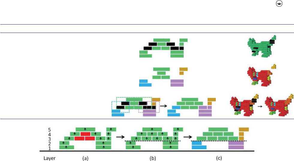
3.1.1. Segmentation at weakly-connected blocks
We detect weakly-connected blocks as blocks corre-
sponding to the previously dened “weak articulation
points” [11]. Note that a block model can be abstracted
as a graph, where the vertices represent individual blocks
and the edges indicate brick linkage by studs. An artic-
ulation point in graph theory is such a vertex that
when removing it the graph generates more than one
COMPUTER-AIDED DESIGN & APPLICATIONS 295
Table 1. Algorithm and illustrations for segmentation at weakly-connected blocks (black blocks).
Operation 2D Illustration 3D Illustration
Step 1 Detect weakly-connected blocks W in
input model M.
Step 2 Divide M into several block segments by
subtracting W from M.
Step 3 Merge each block w ∈ W into a block
segment that has the largest number
of connections to w.
Figure 2. Segmentation avoiding floating blocks.(a)Detectingfloating blocks (red blocks) along arrows. (b) A pseudo floor is inserted
between the 2nd and 3rd layers. (c) The model is divided into four block segments.
disconnected subgraph. For a block model, to identify
important articulation points, Testuz et al. [11]denea
“weak articulation point” as an articulation point that
connects each subgraph owning a size (number of edges
in subgraph) greater than one.
When designing a block model, previous research [11]
detected “weak articulation points” for reducing them
in optimized model; however, not all “weak articula-
tion points” can be avoided when thin part exists. In
this paper, we nd “weak articulation points” as weakly-
connectedblockstohelpustodivideamodelinto
block segments. Denition of “weak articulation point”
[11]decidesthat,byremovingeachweakly-connected
block, the model can be separated into multiple discon-
nected parts, with each part containing more than one
block. Inspired by this property, in our segmentation (see
algorithm in Tab. 1), all the weakly-connected blocks
detected in Step 1 are removed from the initial model in
Step 2. Then in Step 3, each weakly-connected block is
merged into a block segment that has the largest number
of connections to the block.
3.1.2. Segmentation avoiding floating blocks
We rst extract the blocks that will be in the oating
state during a layer-by-layer, bottom-up assembly. Such
oating blocks are easily detected as follows. As shown in
Fig. 2(a), we visit connected blocks from each bottom-
most block to the top. The allowed visiting direction is
only upward, because in a LEGO model two blocks are
directly connected to each other only if they overlap each
other. The blocks that have not been visited by the end are
oating blocks.Fig.2(a) illustrates a simple LEGO model
in 2D with oating blocks (colored in red).
This process for detecting oating blocks uses basically
a breath-rst search algorithm. By default, as shown in
Fig. 2a, there is only one bottom, hence the search starts
from all the bottommost blocks (i.e., initial search keys)
andtravelsthroughthewholemodel.Ifallowingone
more bottom, as shown in Fig. 2b, the original model is
segmented, causing an independent search inside each
block segment.
Ournaltargetistoensurethattherearenooating
blocks in each component generated. Here, we introduce
two strategies to achieve this goal. One is a direct way,
the other indirect. The direct way is to explicitly sep-
arate the oating blocks as components. Note that, in
Fig. 2(a), if we treat the oating blocks (colored in red)
and the rest (colored in green) as two dierent compo-
nents, each component contains no oating blocks inside.
Onthecontrary,theindirectwayisseparatingthemodel
by horizontal planes until no oating block exists as illus-
trated in Fig. 2(b). The dashed line shows the horizontal
plane used to separate the model into components. This
separation works as if we had inserted a working oor
between the 2nd and 3rd layers. We call this separating
plane a pseudo oor.InFig.2(c), due to the separation
by the pseudo oor, four independent components are
obtained, and each can be assembled from the bottom to
the top without any oating block.Soweknowthatwe
have eliminated the oating blocks by inserting a pseudo

296 M. ZHANG ET AL.
Table 2. Algorithm and illustrations for segmentation avoiding floating blocks.
Operation 2D Illustration 3D Illustration
Step 1 For each l, calculate a C
floating
(l) by pre-inserting one
horizontal pseudo floor between the l-th and (l+1)-th
layers. Then insert pseudo floors where C
floating
(l)takes
on local-minima.
Step 2 Indirect segmentation: divide the input model by the
inserted pseudo floors.
Step 3 Direct segmentation: detect floating blocks, and then
explicitly separate them as new block segments.
oor at an appropriate location. In Fig. 2,suchalocation
is between the 2nd and 3rd layers. However, sometimes
one pseudo oor mightbenotenoughtoeliminateallthe
oating blocks; we might require more, or in an extreme
case, one pseudo oor under each layer.
Now we have two strategies to generate components
with no oating blocks inside. We further combine both
strategies to reduce the amount of block segments,which
will benet a more precise instruction. We do so by apply-
ingindirectwayrst,however,notforeliminatingall
oating blocks, but for reducing oating blocks reasonably
by inserting a few eective pseudo oors.Afterthat,we
use the direct way to handle the unreduced oating blocks.
The problem now becomes how to select eective
pseudo oors. We nd that inserting a pseudo oor at an
appropriate location (e.g., between the 2nd and 3rd layers
in Fig. 2) is important. This location is important because
if a pseudo oor is inserted elsewhere, oating blocks
below the pseudo oor cannot be eliminated. To nd such
an appropriate location, we introduce an index C
oating
(l), which equals the number of oating blocks had by
inserting a pseudo layer between the l-th and (l+1)-th
layers for l = 0, 1, 2, ... (l = 0 means the ground
oor). By evaluating the value of C
oating
for all possi-
ble l,wechoosetoinsertpseudo oors where the value
of C
oating
takes on local-minima. We do so because each
local-minimum of C
oating
indicates a horizontal separa-
tion which can better reduce oating blocks in the local
area around the pseudo oor. By applying all these separa-
tions at the same time, the initial model is segmented into
several block segments. The algorithm described above
is summarized in Tab. 2 with 2D and 3D illustrations.
Note that all oating blocks are not eliminated always by
Step 1. The red blocks in the top row of 3D illustration
are oating blocks when the model is separated by two
pseudo oors (illustrated by dashed lines). On the other
hand, no oating blocks exist in the example illustrated
in 2D after inserting a pseudo oor. Therefore, there are
no dierences between middle and bottom rows of 2D
illustrations.
These separations caused by this algorithm result in
unnecessarily-small block segments (e.g., the brown and
the purple block segments in 2D illustration in Tab. 2,
these block segments can be combined without generating
any oating block). In next subsection, we will describe a
strategy to adjust these over-segmentations.
3.1.3. Making components
The initial model is segmented using the two approaches
mentioned above. Based on these segmentations, the
components are generated. As described in the algorithm
in Tab. 3,werstapplythetwosegmentationstothe
model (Step 1). Then we generate components by divid-
ing the model along the boundaries of the segmentations
(Step 2). If oating blocks remain, we separate them as
individual components. Because this generates tiny com-
ponents, we merge them to reduce the number of com-
ponents (Step 3). This step is divided into following four
sub-steps.
i) Find a component “A” which touches a pseudo oor,
or contains only one or two blocks;
ii) Find a component “B” which connects component
“A”;
iii) Merge component “A” and “B” only if the merged
component does not generate additional oating
blocks;
iv) Repeat i) to iii) until all possible merge operations
are done.
Tab. 3 illustratesourwaytoobtaincomponentscon-
taining no oating block. However, theoretically, other
results for components (see Fig. 3)canachievethesame
goal if other features (e.g., recognizability of a compo-
nent, equilibrium of a component) are not considered.
COMPUTER-AIDED DESIGN & APPLICATIONS 297
Table 3. Algorithm and illustrations for making components from block segments. In Step 3, black arrows upward indicate successful
merging. We also show some failed merging indicated by red arrows in 2D illustration.
Operation 2D Illustration 3D Illustration
Step 1 Apply the two segmentation algorithms to the
model: driven by weakly-connected blocks
(left), and avoiding floating blocks (right).
Step 2 Generate components by dividing the model
along the boundaries in both segmentations
generated by Step 1.
Step 3 Merge components as much as possible,
ensuring no floating block is generated.
Figure 3. Different results for components containing no floating block.
In the future, improvements can be made to satisfy more
benecialfeaturesinacomponent.
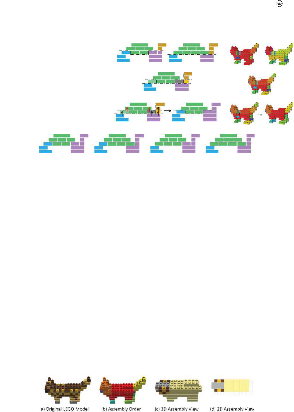
3.2. Making a component-driven instruction
After the LEGO model has been divided into compo-
nents, we start to make an instruction guide for assembly.
By now it is ensured that no oating blocks exist in any
component. Hence, we can simply assemble each compo-
nent in bottom-to-top order, and focus only on the order
of combining components. Among the components, we
dene a joint component as one connecting two or more
other components. The assembly order of components is
decided according to the following priorities:
i) the number of connected components
ii) the number of blocks contained in the component
iii) the number of connected joint components
iv) the distance from the bottommost block (smaller
has higher priority).
Ifvaluei)isthesameforeachcomponent,valueii)is
used to decide the priority. Furthermore, if value ii) is the
same for each component, value iii) is used, and so on.
Finally, if symmetrical components-pairs exist, the order
of components is further adjusted to ensure successive
assembly of such symmetric component-pairs.
After deciding the assembly order of the components,
we generate a graphical instruction guide. To prepare
the user for the assembly ow, the guide rstly switches
from the original LEGO model (Fig. 4(a)) to the com-
pleted model showing colors assigned from blue to red
to the components according to their priority (Fig. 4(b)).
After that, the user begins assembling the rst compo-
nent (the red one in Fig. 4(b)). The assembly procedure
of each component is displayed in an interactive 3D view
(Fig. 4(c)) and a static top-view (Fig. 4(d)). Both views
are simultaneously updated step-by-step. In both views,
blocks in the active component (the component being
assembled) are rendered in the original color, but already
assembled components are rendered in a customized
color (beige in Fig. 4(c, d)). Showing the already assem-
bled components with the active component helps users
to understand their relative positions. Visibility of blocks
during assembling process is important. Because each
component generated in our method can be assembled
layer-by-layer, a 2D view which shows blocks in current
assembling layer (Fig. 4(d)) always ensures the visibility
Figure 4. Our graphical instruction guide.
298 M. ZHANG ET AL.
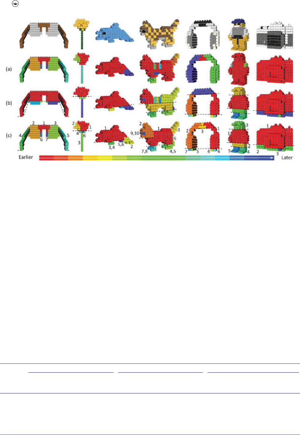
Figure 5. Generation and ordering of components in different test models (top row). (a) Block segments separated at weakly-connected
blocks. (b) Block segments avoiding floating blocks. (c) Final components generated. Assembly order of final components, as marked by
numbers, is associated with a specific color in a color map varying from red (built first) to blue (built last).
of all blocks, even though these blocks might be occluded
in 3D view.
4. Results and discussion
We developed a prototype system to evaluate our method.
It was implemented using C++ and tested on a laptop
with a 2.40-GHz Intel Core (TM) i5-2430M processor, 8
GB RAM, and NVIDIA NVS 4200M GPU.
As far as we know, benchmark containing dierent
block models (e.g., block models designed in dierent
resolutions, block models fragile to varying degrees) has
not been discussed before. To build such a benchmark is
noteasy.Inthispaper,ourproposedmethodismainly
designed for fragile block models. Because the fragile
structure is normally found in block models designed
in low resolution, low-resolution block models are used
to evaluate our proposed method. We prepared seven
low-resolution block models (see Fig. 5)createdbyamini
block artwork design system [12]. These test examples are
fragile to varying degrees, i.e., weakly-connected blocks
intheseblockmodelsarecounteddierently(seeTab.4).
4.1. Generation and ordering of components
Segmentation in our method is driven by weakly-
connected blocks and pseudo oors found in input model.
As shown in Tab. 4, the number of weakly-connected
blocks ranged from 0 (camera) to 14 (sunglasses) in our
test models. After the segmentation at weakly-connected
blocks, the number of block segments ranged from 1
(camera) to 12 (cat). Fig. 6 shows the graph of R
oating
(l), which is the normalized value of C
oating
(l)divided
bytotalnumberofblocksinthemodelsothatit
takes between 0 to 1. For example, if no oating block
exists when a pseudo oor is inserted between l-th and
(l+1)-th layers, R
oating
(l) takes zero; if half of all
blocks are oating, R
oating
(l) takes 0.5. By observing
Table 4. Statistics of test models.
Segmentation at weakly-connected blocks Segmentation avoiding floating blocks Making components
Test model
#ofweakly-
connected blocks
#ofblocksegments
generated (Fig. 5(a))
# of pseudo floors
(local-minima)
#ofblocksegments
generated (Fig. 5(b))
# of components by
overlapping block
segments
# of components
after merging
(Fig. 5(c))
sunglasses 14 7 1 5 11 7
flower 12 4 1 4 6 6
dolphin 1 2 1 5 6 5
cat712216 20 10
headphones 10 3 2 11 13 11
Legoman 5 4 3 6 8 6
camera 0 1 1 3 3 3

COMPUTER-AIDED DESIGN & APPLICATIONS 299
thegraph,wecanndthatmosttestmodels(except
for Legoman) have only one local-minimum or two
local-minima. Detailed information is shown in mid-
dle column of Tab. 4. Although both segmentation steps
result in unnecessarily tiny components (Fig. 5(a, b)), our
merging strategy successfully combines tiny components
intolargeonesforbetterresults(Fig.5(c)). Details can be
found in right column of Tab. 4.
Figure 6. Graph of R
floating
(l),whichtakesratiooffloating blocks
in whole blocks.
Note that Fig. 5 revealsanimportantfeatureof
our component generation method: segmentation along
the horizontal pseudo oor/oors mightbelocally
unwise sometimes (see sunglasses, dolphin and cat in
Fig. 5b); however, segmentation along horizontal pseudo
oor/oors is able to be revised locally, because a wise
remerging is possible due to a wise segmentation of exist-
ing block segments at local disjunctions. Currently, local
disjunctions are identied by weakly-connected blocks in
fragileblockmodel.Inthefuture,forablockmodelbeing
not fragile, other ecient segmentation methods can also
be easily integrated into our current method.
Assembly order of components determined by our
method is illustrated in Fig. 5(c) as well. As expected, joint
components aretobebuiltearlier(inawarmercolor),and
symmetric component-pairs to be built successively are
insimilarcolors.Thisdemonstratestheeectivenessof
our ordering.
4.2. Auto-generation of instruction guide
Tab. 5 compares the instruction guide generated by our
method with those generated by LEGO Digital Designer
[7] and LEGO Instruction Creator [8]. We used in our
test the cat model shown in Fig. 5,whichconsistsof93
blocks and 7 weakly-connected blocks in total. On the
onehand,wefoundthattheinstructionguidegenerated
by LEGO Instruction Creator showed some steps with
oating blocks, while our layer-by-layer assembly inside
each component avoided oating blocks. On the other
hand, we found in the test that the assembly starting from
the feet was breakable, because earlier-built weak parts
of the feet interfered with the smooth assembly of the
rest.However,unliketheothertwosystemswhichdid
not generate separate components for the feet, in our
instruction guide, the assembly of the separate foot com-
ponents was near the end, and thus, it seldom aected the
assembly of other components.
We recruited four undergraduate volunteers to test
the time eciency of the instruction guides generated
by our system and LEGO Digital Designer. The results
showed that all subjects completed the cat model in much
less time when using our instructions. The average time
needed to complete the model with our instructions was
17 min, which is about 60% of the time needed with
LEGO Digital Designer’s instructions.
5. Conclusions and future work
To help the ecient assembly of fragile LEGO mod-
els, we proposed a method for automatic generation of
component-based building instructions. We divide up
a model into components by considering segmentation
at both the weakly-connected blocks and the incoher-
ent spots identied by oating blocks.Weimplemented
our method and evaluated the eciency of the instruc-
tions it generated for several models. We also compared
the instruction guide generated by our prototype system
with those generated by the well-known LEGO Digi-
tal Designer, and another software tool called LEGO
Instruction Creator.
In this paper, we mainly focus on low-resolution block
models, which are usually small enough to be assembled
insideourhands.Itseemsthatourassemblyeciency
has not been greatly troubled by the equilibrium of com-
ponents. However, to make our proposed method more
compatible with various kinds of block models, we can
evolve our component generation to satisfy more require-
ments, e.g., components with more perceivable shapes,
the static equilibrium of component during assembly.
Moreover, a benchmark of block models is expected to
Table 5. Step-by-step instructions created by three systems.
# of components
Max/Min # of blocks in
component
Instructions steps for
component With first block for
Our system 10 (see Fig. 5) 53/1 layer-by-layer body
LEGO Digital Designer 2 (body & tail) 89/4 block-by-block foot
LEGO Instruction Creator 1 (whole) 93 layer-by-layer foot

300 M. ZHANG ET AL.
be built to facilitate the evaluation of a LEGO-related
method all-around. Finally, to make the automatically
generated instructions more user-friendly, diverse nota-
tions shown in manually drawn instructions might be
considered.
ORCID
Man Zhang http://orcid.org/0000-0003-2328-7262
Yuki Igarashi
http://orcid.org/0000-0001-5025-8526
Yoshihiro Kanamori
http://orcid.org/0000-0003-2843-1729
Jun Mitani
http://orcid.org/0000-0002-1596-844X
References
[1] Agrawala,M.;Li,W.;Berthouzoz,F.:Designprinciples
for visual communication, Commun. ACM, 54(4), 2011,
60–69. http://dx.doi.org/10.1145/1924421.1924439
[2] Agrawala,M.;Phan,D.;Heiser,J.;Haymaker,J.;Klingner,
J.;Hanrahan,P.;Tversky,B.:Designingeectivestep-
by-step assembly instructions, ACM Transactions on
Graphics (Proc. SIGGRAPH 2003), 22(3), 2003, 828–837.
http://dx.doi.org/10.1145/882262.882352
[3] Gupta, A.; Fox, D.; Curless, B.; Cohen, M.: DuploTrack: A
real-time system for authoring and guiding duplo block
assembly, Proc. UIST 2012, New York, NY, USA, 2012,
389–402. http://dx.doi.org/10.1145/2380116.2380167
[4] Heiser,J.;Phan,D.;Agrawala,M.;Tversky,B.;Hanrahan,
P.: Identication and validation of cognitive design prin-
ciples for automated generation of assembly instructions,
Proc. AVI’04, Gallipoli (Lecce), ITALY, 2004, 311–319.
http://dx.doi.org/10.1145/989863.989917
[5] Hong, J.-Y.; Way, D.-L.; Shih, Z.-C.; Tai, W.-K.; Chang, C.-
C.:Innerengravingforthecreationofabalancedlego
sculpture, The Visual Computer, 2015, 1–10.
[6] Kuo, M.-H; Lin, Y.-E; Chu, H.-K; Lee, R.-R; Yang,
Y.-L: Pixel2Brick: Constructing Brick Sculptures from
Pixel Art, Comput. Graph. Forum, 34(7), 2015, 339–348.
http://dx.doi.org/10.1111/cgf.12772
[7] Lego digital designer, http://ldd.lego.com,LEGO.
[8] Lego instruction creator, http://bugeyedmonkeys.com/
lic_info, 2010 Remi Gagne.
[9] Luo, S.-J.; Yue, Y.-H.; Huang, C.-K.; Chung, Y.-H.;
Imai, S.; Nishita, T.; Chen, B.-Y.: Legolization: Opti-
mizing LEGO Designs, ACM Transactions on Graphics
(Proc. SIGGRAPH Asia 2015), 34(6), 2015, p.222:1–12.
http://dx.doi.org/10.1145/2816795.2818091
[10] Nanoblock, http://www.diablock.co.jp/nanoblock/catalog/
minicollection,KawadaCo.Ltd.
[11] Testuz, R.; Schwartzburg, Y.; Pauly, M.: Automatic genera-
tion of constructable brick sculptures, Proc. Eurographics
2013, Girona, SPAIN, 2013, 81–84. http://dx.doi.org/10.
2312/conf/EG2013/short/081-084
[12] Zhang, M.; Igarashi, Y.; Kanamori, Y.; Mitani, J.: Design-
ing mini block artwork from colored mesh, Proc. Smart
Graphics 2015, Chengdu, CHINA, 2015, p.2:1–12.
