
Quick Reference
Original Instructions
Connected Components Workbench Software Guide for
Studio 5000 Logix Designer Application Users
Terminology and Workflow Comparison
Topic Page
Summary of Changes 2
Comparison of Terms in Connected Components Workbench Software and
Studio 5000 Logix Designer Application
5
Uploading from an Existing Controller for the First Time 6
Open an Existing Offline Project 7
Open a Saved Offline Project 7
Downloading an Offline Project to a Controller 8
Going Online with a Controller 9
Password Protecting Future Controller Access 10
Online Monitoring of Programs and Tags 11
Forcing I/O 12
Make Online Edits 12
Going Offline from a Controller 13
Save an Offline Project 13
Generate a Project Printout 14
Change the Offline File Control Catalog Number and/or Version 15
Create a New Controller Project 16
Import an Add-On Instruction or Subroutine to a Project 28
Use an Add-On Instruction or Subroutine in a Program 29
Export and Import Tags 30
Keyboard Toggle Bit Shortcut 32
Cross Reference Tags 32
Rename Tags 32
Additional Resources 33

2 Rockwell Automation Publication 9328-QR001C-EN-E - July 2022
Connected Components Workbench Software Guide for Studio 5000 Logix Designer Application Users Quick Reference
Summary of Changes
This publication contains the following new or updated information. This list includes substantive updates only and is not intended to reflect
all changes.
Topic Page
Updated template Throughout
Updated screen captures Throughout
Updated step 3 in Uploading from an Existing Controller for the First Time 6
Updated Password Protecting Future Controller Access 10
Updated step 2 in Online Monitoring of Programs and Tags 11
Added tip to step 1 in Make Online Edits 12
Updated Save an Offline Project 13
Updated Generate a Project Printout 14
Added tip to Verify Rung Settings for Optimal Viewing 18
Updated step 1 in Select Logix Theme and View Instruction Mapping 19
Added topic Add a Branch to the Ladder Instruction 21
Updated Assign a Tag to a Ladder Instruction 22
Updated tips in Copy and Paste a Ladder Rung From Studio 5000 Logix Designer
Application
25, 26
Added tip to Export and Import Tags 31
Removed topic Data Types 32

Rockwell Automation Publication 9328-QR001C-EN-E - July 2022 3
Table of Contents
Summary of Changes . . . . . . . . . . . . . . . . . . . . . . . . . . . . . . . . . . . . . . . . . . . . . . . . . . . . . . . 2
Comparison of Terms in Connected Components Workbench Software and
Studio 5000 Logix Designer Application . . . . . . . . . . . . . . . . . . . . . . . . . . . . . . . . . . . . . . . 5
Uploading from an Existing Controller for the First Time . . . . . . . . . . . . . . . . . . . . . . . . . 6
Open an Existing Offline Project . . . . . . . . . . . . . . . . . . . . . . . . . . . . . . . . . . . . . . . . . . . . . . 7
Open a Saved Offline Project. . . . . . . . . . . . . . . . . . . . . . . . . . . . . . . . . . . . . . . . . . . . . . . . . 7
Downloading an Offline Project to a Controller. . . . . . . . . . . . . . . . . . . . . . . . . . . . . . . . . . 8
Going Online with a Controller. . . . . . . . . . . . . . . . . . . . . . . . . . . . . . . . . . . . . . . . . . . . . . . . 9
Password Protecting Future Controller Access . . . . . . . . . . . . . . . . . . . . . . . . . . . . . . . . 10
Online Monitoring of Programs and Tags. . . . . . . . . . . . . . . . . . . . . . . . . . . . . . . . . . . . . . 11
Forcing I/O. . . . . . . . . . . . . . . . . . . . . . . . . . . . . . . . . . . . . . . . . . . . . . . . . . . . . . . . . . . . . . . 12
Make Online Edits . . . . . . . . . . . . . . . . . . . . . . . . . . . . . . . . . . . . . . . . . . . . . . . . . . . . . . . . . 12
Going Offline from a Controller . . . . . . . . . . . . . . . . . . . . . . . . . . . . . . . . . . . . . . . . . . . . . . 13
Save an Offline Project. . . . . . . . . . . . . . . . . . . . . . . . . . . . . . . . . . . . . . . . . . . . . . . . . . . . . 13
Generate a Project Printout. . . . . . . . . . . . . . . . . . . . . . . . . . . . . . . . . . . . . . . . . . . . . . . . . 14
Change the Offline File Control Catalog Number and/or Version . . . . . . . . . . . . . . . . . . 15
Create a New Controller Project . . . . . . . . . . . . . . . . . . . . . . . . . . . . . . . . . . . . . . . . . . . . . 16
Select the Controller Catalog Number and Version. . . . . . . . . . . . . . . . . . . . . . . . . . 16
Configure the Communication Parameters. . . . . . . . . . . . . . . . . . . . . . . . . . . . . . . . 17
Add and Configure any Plug-in and/or Expansion I/O Modules. . . . . . . . . . . . . . . . 17
Verify Rung Settings for Optimal Viewing . . . . . . . . . . . . . . . . . . . . . . . . . . . . . . . . . 18
Add a New Ladder Program . . . . . . . . . . . . . . . . . . . . . . . . . . . . . . . . . . . . . . . . . . . . . 19
Open a Ladder Program . . . . . . . . . . . . . . . . . . . . . . . . . . . . . . . . . . . . . . . . . . . . . . . . 19
Select Logix Theme and View Instruction Mapping . . . . . . . . . . . . . . . . . . . . . . . . . 19
Add a Ladder Instruction on a Rung . . . . . . . . . . . . . . . . . . . . . . . . . . . . . . . . . . . . . . 20
Add a Branch to the Ladder Instruction . . . . . . . . . . . . . . . . . . . . . . . . . . . . . . . . . . . 21
Assign a Tag to a Ladder Instruction . . . . . . . . . . . . . . . . . . . . . . . . . . . . . . . . . . . . . 22
Add an Instruction Block on a Rung and Assign its Input and Output Parameters 22
Add a Rung and Ladder Instructions Using LD Text Input . . . . . . . . . . . . . . . . . . . . 24
Copy and Paste a Ladder Rung From Studio 5000 Logix Designer Application. . . 25
Password Protect Program (Optional) . . . . . . . . . . . . . . . . . . . . . . . . . . . . . . . . . . . . 27
Verify Controller Before Download . . . . . . . . . . . . . . . . . . . . . . . . . . . . . . . . . . . . . . . 28

4 Rockwell Automation Publication 9328-QR001C-EN-E - July 2022
Table of Contents
Import an Add-On Instruction or Subroutine to a Project . . . . . . . . . . . . . . . . . . . . . . . . 28
Use an Add-On Instruction or Subroutine in a Program. . . . . . . . . . . . . . . . . . . . . . . . . . 29
Export and Import Tags . . . . . . . . . . . . . . . . . . . . . . . . . . . . . . . . . . . . . . . . . . . . . . . . . . . . 30
Keyboard Toggle Bit Shortcut . . . . . . . . . . . . . . . . . . . . . . . . . . . . . . . . . . . . . . . . . . . . . . . 32
Cross Reference Tags . . . . . . . . . . . . . . . . . . . . . . . . . . . . . . . . . . . . . . . . . . . . . . . . . . . . . 32
Rename Tags. . . . . . . . . . . . . . . . . . . . . . . . . . . . . . . . . . . . . . . . . . . . . . . . . . . . . . . . . . . . . 32
Additional Resources . . . . . . . . . . . . . . . . . . . . . . . . . . . . . . . . . . . . . . . . . . . . . . . . . . . . . . 33

Rockwell Automation Publication 9328-QR001C-EN-E - July 2022 5
Connected Components Workbench Software Guide for Studio 5000 Logix Designer Application Users Quick Reference
Comparison of Terms in Connected Components Workbench Software and
Studio 5000 Logix Designer Application
Connected Components Workbench Software Terms in Studio 5000 Logix Designer Application
Connected Components Workbench Software Studio 5000 Logix Designer Application
Accept Changes Accept Edits
Build Verify and Assemble
CCWARC File ACD File
Connect Go Online
Connected Online
Connection Browser RSWho
Connection Path Project Path
Discard Changes Cancel Edits
Disconnect Go Offline
Disconnected Offline
Discover Upload and Go Online
Download with Project Values Download
Global Variable Controller Tag
Lock Force
Project Organizer Controller Organizer
Run Mode Change (RMC) Online Editing
Test Changes Test Edits
Toolbox, Instruction Toolbar Language Element Toolbar
Upload with Project Values Upload
User-defined Functions (UDFs) Subroutine
User-defined Function Blocks (UDFBs) Add-On Instructions (AOI)
Variable Tag
Studio 5000 Logix Designer Application Terms in Connected Components Workbench Software
Studio 5000 Logix Designer Application Connected Components Workbench Software
Accept Edits Accept Changes
ACD File CCWARC File
Add-On Instructions (AOI) User-defined Function Blocks (UDFBs)
Cancel Edits Discard Changes
Controller Organizer Project Organizer
Controller Tag Global Variable
Download Download with Project Values
Force Lock
Go Offline Disconnect
Go Online Connect
Language Element Toolbar Toolbox, Instruction Toolbar
Offline Disconnected
Online Connected
Online Editing Run Mode Change (RMC)
Project Path Connection Path
RSWho Connection Browser
Subroutine User-defined Functions (UDFs)
Tag Variable
Test Edits Test Changes
Upload Upload with Project Values
Upload and Go Online Discover
Verify and Assemble Build

6 Rockwell Automation Publication 9328-QR001C-EN-E - July 2022
Connected Components Workbench Software Guide for Studio 5000 Logix Designer Application Users Quick Reference
Uploading from an Existing Controller for the First Time
The term Discover in Connected Components Workbench™ software is used for uploading from an existing controller for the first time.
1. Open Connected Components Workbench software (under All Programs/Rockwell Automation/CCW).
2. Click Discover… on the Start Page.
3. Browse to and select the desired Micro800™ controller in the Connection Browser window, then click OK.
4. The controller image is uploaded into a new project and includes any plug-ins and expansion I/O modules that are physically
connected to the controller. If the project in the controller does not have the physical modules that are configured within the image,
then you get the error message, “The current project content does not match the content in the connected controller. The software
will not automatically go online (Connect) with the controller.” In this case, the best thing to do is to follow up with an Upload from the
controller, which syncs up the offline image with the online image. The software then automatically goes online (Connect) with the
controller.
IMPORTANT If you get a Connection Error popup window or if the upload fails because “The imported database version is
more recent than the product database version.”, then most likely the controller was programmed with a newer
version of Connected Components Workbench software. Update your Connected Components Workbench
software to the latest version and try again.
The upload can also fail if you previously did not download the project source code to the controller. The
Download Source Code option is available in Connected Components Workbench software version 13 or later, in
the Micro800 controller General page.

Rockwell Automation Publication 9328-QR001C-EN-E - July 2022 7
Connected Components Workbench Software Guide for Studio 5000 Logix Designer Application Users Quick Reference
5. You can save the offline project under a name of your choosing by selecting File -> Save Project As….
Open an Existing Offline Project
A Connected Components Workbench software project consists of a ‘ProjectName’ folder that contains a number of subdirectory folders and
files. They must all be present to open the ProjectName.ccwsln file.
1. Open Connected Components Workbench software (under All Programs/Rockwell Automation/CCW).
2. Click Open Existing… on the Start Page.
3. Browse to and double-click the desired controller project folder, then double-click the CCWSLN file within that folder to open the
project.
Open a Saved Offline Project
A Connected Components Workbench software CCWARC archive file is equivalent to a Logix ACD file. One file contains everything that is
required to open the Connected Components Workbench software project. To do so, you must first import the file.
1. Open Connected Components Workbench software (under All Programs/Rockwell Automation/CCW).
2. To import and open the project, select File -> Import Project…, then browse to and double-click the desired CCWARC file.
It is recommended to use the single CCWARC archive file for copying and sharing projects, instead of copying the entire
folder that contains the CCWSLN file.

8 Rockwell Automation Publication 9328-QR001C-EN-E - July 2022
Connected Components Workbench Software Guide for Studio 5000 Logix Designer Application Users Quick Reference
Downloading an Offline Project to a Controller
1. With the offline project open and the Micro800 controller window displayed, check if there is a connection (project) path for the
controller on the upper right-hand corner of the screen. If present, that path is used to attempt to connect with the controller when
you click Download. If the path is no longer valid, click the eraser icon to delete it. Once the path is deleted, or no path was displayed
to begin with, click Download. The Connection Browser (RSWho) window opens for you to select the controller to download to. The
path automatically updates once you select the controller.
2. Two options are presented for downloading – with Project Values or without Project Values. Project Values are a snapshot of the
values of each tag (variable) when the project was last uploaded (assuming the upload used was 'Discover' or 'Upload with Project
Values'). Any tag may also be assigned an initial value, in which case the initial value is always used after a download. Any tag that
does not have an initial value is set to zero when Download (without Project Values) is selected. Unless you intend to zero out every
non-initialized tag, click Download with Project Values.
3. When the download is completed, a request to change the controller to run mode pops up (whether the controller was previously in
run mode or not). Click Yes or No. The software automatically goes online with the controller at this point.
• Download with Project Values is equivalent to the Studio 5000 Logix Designer® application behavior for downloading tag
values, but it takes longer than Download (without Project Values) since almost all tags values must be downloaded. Using
Initial Values on select tags and downloading without Project Values decrease download time.
• To preserve a tag value in the controller from being overwritten or zeroed during download, use the download Data
Protection feature accessible by right-clicking on the controller in the project organizer. Data Protection has precedence
over Initial Value and Project Value.
• During download, Data Protection has precedence over Initial Value, which then has precedence over Project Value.
Connection path Eraser icon

Rockwell Automation Publication 9328-QR001C-EN-E - July 2022 9
Connected Components Workbench Software Guide for Studio 5000 Logix Designer Application Users Quick Reference
Going Online with a Controller
The Connected Components Workbench software term for going online with a controller is Connect.
1. With the offline project open and the Micro800 controller window displayed, check if there is a connection (project) path for the
controller on the upper right-hand corner of the screen. If present, that path is used to attempt to connect with the controller when
you click Connect. If the path is no longer valid, click the eraser icon to delete it. Once the path is deleted, or if no path was displayed
to begin with, click Connect. The Connection Browser (RSWho) window opens for you to select the controller to go online with. The
path automatically updates once you select the controller.
2. If there are any differences between the offline project and the online project, the Download/Upload confirmation window appears.
Choose either to download the current offline project to the controller, or upload the online project and save it as the offline project.
3. When you are online (Connected) with the controller, the word Connected appears on the upper left-hand corner of the screen, and
the button for Connect is replaced with Disconnect (that is, to return offline).
Connection path Eraser icon

10 Rockwell Automation Publication 9328-QR001C-EN-E - July 2022
Connected Components Workbench Software Guide for Studio 5000 Logix Designer Application Users Quick Reference
Password Protecting Future Controller Access
Once online (Connected), the controller can be protected with a password. This feature helps prevent unauthorized access to the
configuration and programming in the controller. The password is 1…64 characters in length for Connected Components Workbench
software version 20 and later (for version 13 and earlier, the password is 8…32 characters in length). Valid characters are uppercase and
lowercase letters, numbers, spaces, and symbols found on the keyboard. This password does not protect the offline file from edits or views.
For this case, you must apply passwords to the individual programs and/or UDFBs. See Password Protect Program (Optional)
on page 27.
1. While online with the controller, click Secure and select Set Password.
2. Enter the Password, then reenter the same password in Confirmation and click OK.

Rockwell Automation Publication 9328-QR001C-EN-E - July 2022 11
Connected Components Workbench Software Guide for Studio 5000 Logix Designer Application Users Quick Reference
Online Monitoring of Programs and Tags
The Connected Components Workbench software term for Online is Connected.
1. Once online with the controller, double-click the program name icon in the Project Organizer of the program that you want to
monitor. Blue is the rung color that is used to indicate that the rung logic is false and red is the rung color that is used to indicate that
the rung logic is true.
2. To monitor the tag values in list format, double-click any tag name to bring up the Variable Selector window. Program tags are listed
under Scope: <Program Name> and user-created controller tags are listed under Scope: <controller name>.
3. To open a separate screen of all local program tags, double-click the Local Variables icon under the program name in the Project
Organizer.
4. To open a separate screen of all global controller tags, double-click the Global Variables icon under the program name in the Project
Organizer.

12 Rockwell Automation Publication 9328-QR001C-EN-E - July 2022
Connected Components Workbench Software Guide for Studio 5000 Logix Designer Application Users Quick Reference
Forcing I/O
The Connected Components Workbench software term for Force is Lock.
While monitoring the I/O tags under Global Variables, select the Lock checkbox for each I/O tag that you want to force on or off. For outputs,
select the Physical Value checkbox to force on the output and deselect the Physical Value checkbox to force off the output. The indicators
for forced outputs on the Micro800 controller correspond to the forced value. For inputs, select the Logical Value checkbox to force on the
input and deselect the Logical Value checkbox to force off the input. The indicators for forced inputs on the Micro800 controller correspond
to the actual input value, not the forced value.
The FORCE indicator on the Micro800 controller is on whenever there is at least one I/O point being forced. All forces are cleared after you
cycle power to the controller.
Make Online Edits
The Connected Components Workbench software term for Online Editing is Run Mode Change (RMC).
1. While monitoring the ladder program, click the Run Mode Change icon. The ladder program changes to appear as if it is offline, even
though the software is still online (Connected).
2. Make your desired changes to the logic and/or tags, then click the Test Changes icon to the right of Run Mode Change to test your
edits.
In Connected Components Workbench software version 13 or later, you can make online edits faster if the project source
code is not downloaded to the controller. However, remember to download the project source code to the controller after
all changes have been made.
Test Changes icon

Rockwell Automation Publication 9328-QR001C-EN-E - July 2022 13
Connected Components Workbench Software Guide for Studio 5000 Logix Designer Application Users Quick Reference
3. To assemble the online edits to make the change permanent, click the Accept Changes icon to the right of Test Changes.
4. To cancel the online edits to undo the changes, click the Discard Changes icon to the far right of Run Mode Change.
Going Offline from a Controller
Double-click the Micro800 controller icon in the Project Organizer to bring up the Micro800 window. Click the Disconnect button on the
upper right-hand corner of the screen to go offline.
Save an Offline Project
In Connected Components Workbench software, when you save a project, a folder is created that contains all the files used in that project.
Alternatively, you can export a project. This method creates a CCWARC archive file that is equivalent to a Logix ACD file in that one file
encapsulates the entire Connected Components Workbench software project. If you want to share projects, we recommend to use the export
project option.
Accept Changes icon
Discard Changes icon
Files created when project is saved Archive file created when project is exported

14 Rockwell Automation Publication 9328-QR001C-EN-E - July 2022
Connected Components Workbench Software Guide for Studio 5000 Logix Designer Application Users Quick Reference
1. To export a project, select File -> Export Project…, browse to the desired directory, and enter a filename (which is given a .ccwarc
extension) to save (archive) the project to.
Generate a Project Printout
To generate a printout of your project, select File -> Document Generator. The Document Generator configuration window appears.

Rockwell Automation Publication 9328-QR001C-EN-E - July 2022 15
Connected Components Workbench Software Guide for Studio 5000 Logix Designer Application Users Quick Reference
Change the Offline File Control Catalog Number and/or Version
You can upgrade the controller project version for the existing controller catalog number to match the installed version of Connected
Components Workbench software. Alternatively, you can change to another controller catalog number at the same controller project version
as the installed version of Connected Components Workbench software. Unlike Logix, the controller firmware revision does not need to
match the controller project version, but it does have to be greater than or equal to it.
1. Open Connected Components Workbench software (under All Programs/Rockwell Automation/CCW).
2. Open an existing project.
3. Right-click the Micro800 controller icon in the Project Organizer and select Change Controller….
4. Enter another Target Project Name and/or Controller Name from the defaults provided. Select your preferred Controller Type
(catalog number) and click OK.

16 Rockwell Automation Publication 9328-QR001C-EN-E - July 2022
Connected Components Workbench Software Guide for Studio 5000 Logix Designer Application Users Quick Reference
Create a New Controller Project
Select the Controller Catalog Number and Version
1. Open Connected Components Workbench software (under All Programs/Rockwell Automation/CCW).
2. Click New… on the Start Page.
3. Enter your desired project name or accept the default name and click Create.
4. Select the catalog number for your controller, choose the desired project Version (typically the latest, but does not have to be. Both
the latest software version and controller firmware revision support all earlier versions of projects), then click Select and click Add
To Project.

Rockwell Automation Publication 9328-QR001C-EN-E - July 2022 17
Connected Components Workbench Software Guide for Studio 5000 Logix Designer Application Users Quick Reference
Configure the Communication Parameters
On the Micro800 controller page, click Ethernet and/or Serial Port to configure the desired communication settings.
Add and Configure any Plug-in and/or Expansion I/O Modules
1. Right-click the blank plug-in or expansion module slot on the controller graphic and select the module to add.
2. Alternatively, from the menu you can right-click either an < Empty > slot under Plug-in Modules or an < Available > slot under
Expansion Modules (Micro850® or Micro870® controller) and select the module to add.

18 Rockwell Automation Publication 9328-QR001C-EN-E - July 2022
Connected Components Workbench Software Guide for Studio 5000 Logix Designer Application Users Quick Reference
3. Once you have added the module, the module configuration page appears.
Verify Rung Settings for Optimal Viewing
Under Tools -> Options, verify that the Ladder Diagram (LD) Rung Settings for Coil Alignment is set to False and for Fit to Window Width is
set to True.
If you do not want the Variable Selector window to appear automatically when you add an instruction, under Editor Setting, set
Automatically Invoke Variable/Block to False.

Rockwell Automation Publication 9328-QR001C-EN-E - July 2022 19
Connected Components Workbench Software Guide for Studio 5000 Logix Designer Application Users Quick Reference
Add a New Ladder Program
In the Project Organizer, right-click Programs and select Add -> New LD: Ladder Diagram.
Open a Ladder Program
Double-click the ladder program name, for example Prog1 (default name, which can be renamed), and the ladder program opens up with one
blank rung.
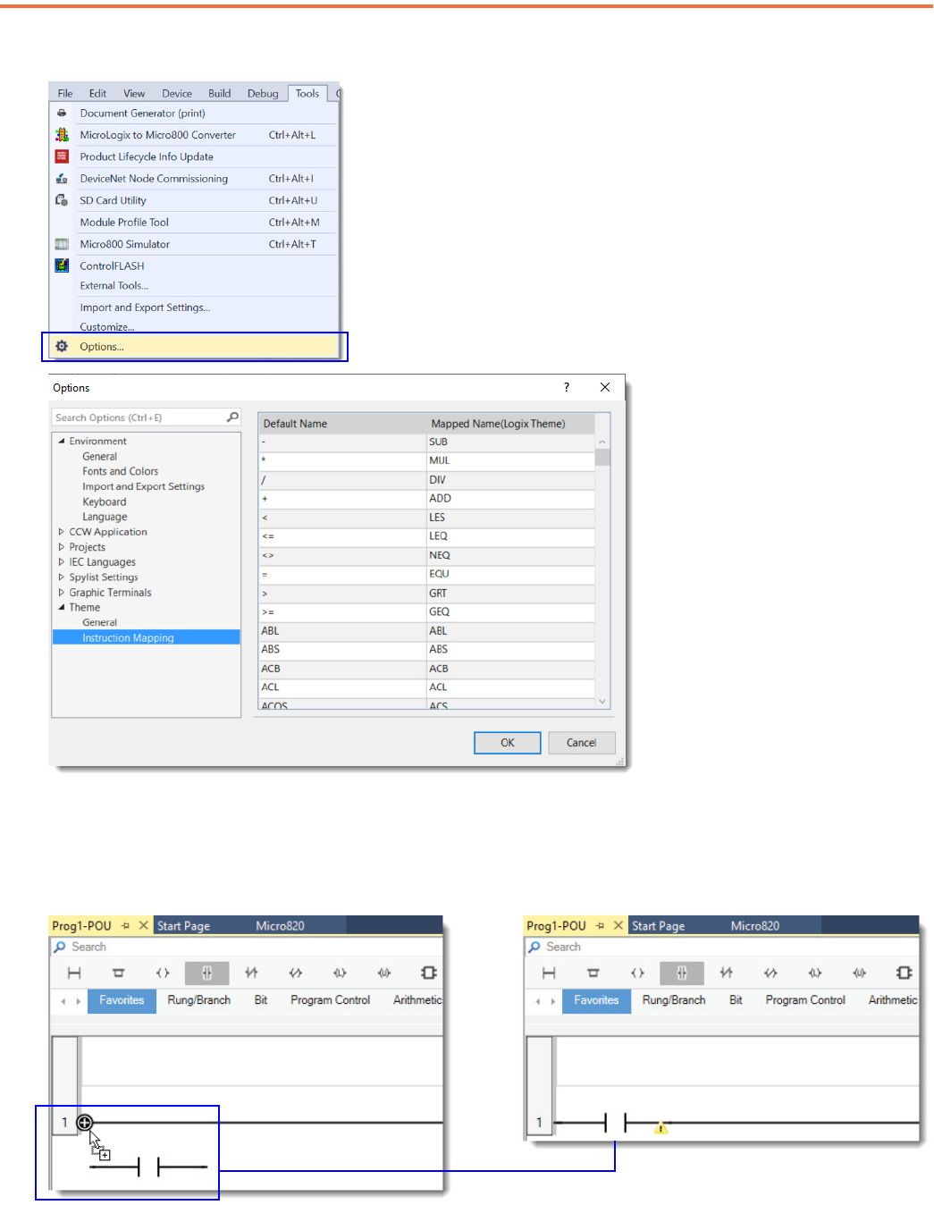
Select Logix Theme and View Instruction Mapping
1. Use the Theme pull-down menu to change the theme from Default to Logix. The Logix theme provides the Controller Organizer view
and uses Logix names and symbols for all ladder instructions that have the same functionality as Logix instructions.
20 Rockwell Automation Publication 9328-QR001C-EN-E - July 2022
Connected Components Workbench Software Guide for Studio 5000 Logix Designer Application Users Quick Reference
2. An instruction-mapping table of Default Names to Logix Theme Names can be found under Tools -> Options -> Theme -> Instruction
Mapping.
Add a Ladder Instruction on a Rung
From the Instruction Library directly above the ladder rung, click-and-drag a ladder instruction (like Direct Contact in the Favorites group)
to the rung until a '+' icon appears where the instruction is to be placed, then release the mouse button.

Rockwell Automation Publication 9328-QR001C-EN-E - July 2022 21
Connected Components Workbench Software Guide for Studio 5000 Logix Designer Application Users Quick Reference
Add a Branch to the Ladder Instruction
Branching is performed differently in Connected Components Workbench software. To expand a branch, you must add instructions to it. You
cannot drag a branch to expand it.
From the Instruction Library directly above the ladder rung, click-and-drag a branch in the Favorites group to the rung until a '+' icon
appears where the branch is to be placed, then release the mouse button.
Alternatively, you can select an instruction on the rung and press Ctrl+7 to add a branch.
To create complex branches in Connected Components Workbench software, instructions must be created in the branch to expand the
branch. Follow the steps shown in the example to create the nested branches.
1312
10
9
8
76
5
4
3
2
1
9 11
10

22 Rockwell Automation Publication 9328-QR001C-EN-E - July 2022
Connected Components Workbench Software Guide for Studio 5000 Logix Designer Application Users Quick Reference
Assign a Tag to a Ladder Instruction
The Connected Components Workbench software term for Tag is Variable.
After placing the instruction, the Variable Selector window opens to let you assign a tag (variable) or to create one. The Scope: <controller
name> screen contain the default system and I/O controller tags. The Scope: <program name> screen contains user-created tags that are
scoped to this program. The Scope: <controller name> screen also contains user-created tags that are controller-scoped.
To assign a tag, click the appropriate scope, select the desired tag, and click OK. Use the Filter function to narrow down the search of tags.
To create a tag, choose either <controller name> or <program name> under “Scope” to determine whether the new tag is scoped globally
or locally. Enter a name for the new tag in the Name box and click OK.
Add an Instruction Block on a Rung and Assign its Input and Output Parameters
1. Select the program group in the Instruction Library that contains the desired instruction. Click-and-drag the instruction to the rung
until a '+' icon appears where the instruction is to be placed, then release the mouse button.
Alternatively, you can double-click the name of the instruction in the Instruction Library to place it on the rung after the last
instruction. If you are unsure in which program group the instruction is located, use the Search box to find the instruction.

Rockwell Automation Publication 9328-QR001C-EN-E - July 2022 23
Connected Components Workbench Software Guide for Studio 5000 Logix Designer Application Users Quick Reference
2. Hover the mouse cursor over the instruction to identify the data types of the input and output parameters. For ATN (Arc Tangent), both
parameters must be of data type REAL.
3. Double-click the lower half of the input parameter box to bring up the Variable Selector screen. From here, you can select an existing
REAL tag (variable) or create one and press Enter.
4. Similarly, double-click the lower half of the output parameter box to bring up the Variable Selector screen. From here, you can select
an existing REAL tag (variable) or create one and press Enter.

24 Rockwell Automation Publication 9328-QR001C-EN-E - July 2022
Connected Components Workbench Software Guide for Studio 5000 Logix Designer Application Users Quick Reference
Add a Rung and Ladder Instructions Using LD Text Input
1. Click the LD Text Input toggle to expand the LD Text Input window. The instruction text for rung 1 is displayed.
2. Place your cursor at the end of the rung 1 text and press Enter to create rung 2.

Rockwell Automation Publication 9328-QR001C-EN-E - July 2022 25
Connected Components Workbench Software Guide for Studio 5000 Logix Designer Application Users Quick Reference
3. In the blank text box for rung 2, type in: “BST XIC _IO_EM_DI_00 TON TON_1 NXB XIC _IO_EM_DO_06 BND XIO _IO_EM_ DI_01 OTE
_IO_EM_DO_06” to program the rung.
Copy and Paste a Ladder Rung From Studio 5000 Logix Designer Application
1. Right-click the desired rung within Studio 5000 Logix Designer application and select Copy Rung.
2. With the LD Text Input window expanded, right-click within the box to the right of rung 1 and select Paste.
To make it easier to enter the correct syntax for a branch, auto-completion is available if the TAB key is pressed after
typing “BST”. Auto-completion for a branch inserts a “BST NXB BND”.
Logix instructions such as NOP, SBR, INT, JSR, and AFI are not supported. These instructions appear as undeclared
variables and are assigned as the input or output of an instruction. For more information, see Knowledgebase article
CCW: Logix Theme does not Support NOP, SBR, INT, JSR and AFI instructions, QA44972 available at rok.auto/knowledgebase.
BST = Branch Start
XIC = Examine If Closed (Direct Contact)
TON = On-delay Timer
NXB = Next Branch
BND = Branch End
OTE = Output Energize (Direct Coil)

26 Rockwell Automation Publication 9328-QR001C-EN-E - July 2022
Connected Components Workbench Software Guide for Studio 5000 Logix Designer Application Users Quick Reference
• You can select multiple rungs of ladder logic to copy and paste.
• When you paste the ladder logic, if you have identical variables in your project, these variables are automatically
populated in the instruction. To simplify this process, import the variables into your project before you copy and paste the
ladder logic. For more information on how to import variables, see Export and Import Tags
on page 30.
• ASCII text input allows multiple output coils in series to be entered, which cannot be entered using the graphical editor.
Although Studio 5000 Logix Designer application supports this behavior, Connected Components Workbench software
currently does not, and the output of the coil is always TRUE.

Rockwell Automation Publication 9328-QR001C-EN-E - July 2022 27
Connected Components Workbench Software Guide for Studio 5000 Logix Designer Application Users Quick Reference
Password Protect Program (Optional)
To help prevent unauthorized views and edits of the program, both offline and online, you can assign a password to it. Passwords must
contain 1...8 alphanumeric characters - no spaces or special characters are allowed. To assign, change, and clear program passwords,
Connected Components Workbench Developer Edition software is required.
1. Right-click the program name and select Password.
2. Enter New Password, then reenter the same password in Confirm Password and click OK.
3. Now, whenever the program is opened, whether offline or online, you are prompted to enter the Password. Enter the password and
click OK to proceed.

28 Rockwell Automation Publication 9328-QR001C-EN-E - July 2022
Connected Components Workbench Software Guide for Studio 5000 Logix Designer Application Users Quick Reference
Verify Controller Before Download
The Connected Components Workbench software term for Verify Controller is Build.
1. To verify the controller project, click the Build icon. The Build result is displayed in the Output window at the bottom of the screen.
Only a successfully built project can be downloaded to a controller.
2. If the Build fails, review the error list to determine what must be corrected. Fix the errors and rebuild the project. Repeat this process
until the Build succeeds.
Import an Add-On Instruction or Subroutine to a Project
The Connected Components Workbench software term for an Add-On Instruction is UDFB and for a subroutine is UDF.
1. Right-click the Micro800 controller icon in the Project Organizer and select Import -> Import Exchange File.
Build icon

Rockwell Automation Publication 9328-QR001C-EN-E - July 2022 29
Connected Components Workbench Software Guide for Studio 5000 Logix Designer Application Users Quick Reference
2. Click Browse, browse to and select the desired UDFB file, then click Import.
3. Imported Add-On Instructions and subroutines are listed in the Project Organizer under User-Defined Function Blocks for Add-On
Instructions and User-Defined Functions for subroutines.
Use an Add-On Instruction or Subroutine in a Program
The Connected Components Workbench software term for an Add-On Instruction is UDFB and for a subroutine is UDF.
1. Once an Add-On Instruction or subroutine is imported into a project, its name is listed in the (User defined) group. Select the (User
defined) group, click the Add-On Instruction or subroutine name, then drag-and-drop the Add-On Instruction or subroutine onto the
rung. There is no separate Jump to Subroutine (JSR) instruction needed for UDFs.

30 Rockwell Automation Publication 9328-QR001C-EN-E - July 2022
Connected Components Workbench Software Guide for Studio 5000 Logix Designer Application Users Quick Reference
2. Assign tags (variables) to the instruction input and output parameters.
Export and Import Tags
The Connected Components Workbench software terms for Controller Tags are Global Variables and Local Tags are called Local Variables.
1. To export Controller Tags, right-click the Micro800 controller icon in the Project Organizer and select Export -> Variables. Browse to
the desired directory, enter a filename, and click Save. The file is saved in the Microsoft® Excel® format.

Rockwell Automation Publication 9328-QR001C-EN-E - July 2022 31
Connected Components Workbench Software Guide for Studio 5000 Logix Designer Application Users Quick Reference
2. To export Local Tags, right-click the desired Program icon in the Project Organizer and select Export -> Variables. Browse to the
desired directory, enter a filename, and click Save. The file is saved in the Microsoft Excel format.
3. To import Controller Tags, right-click the Micro800 controller icon in the Project Organizer and select Import -> Variables. Browse to
the desired directory, select the file (in Microsoft Excel format), and click Open.
4. To import Local Tags, right-click the desired Program icon in the Project Organizer and select Import -> Variables. Browse to the
desired directory, select the file (in Microsoft Excel format), and click Open.
To help confirm that variables are imported correctly into your project, edit the data in the file so that it matches the
format that is used by Connected Components Workbench software, before you perform the import.

32 Rockwell Automation Publication 9328-QR001C-EN-E - July 2022
Connected Components Workbench Software Guide for Studio 5000 Logix Designer Application Users Quick Reference
Keyboard Toggle Bit Shortcut
While online with the controller and with a bit instruction selected (indicated by the bright green box around the instruction), use Ctrl+T to
toggle the instruction bit between off and on (and through the Toggle Boolean Value menu selection).
Cross Reference Tags
Select View -> Cross Reference Browser to find where tags (variables) are used. Click (x unused Variables) to open the Unused Variable
Browser, which includes a one-click Delete Unused Variables selection.
Rename Tags
Existing tags (variables) that are renamed are automatically updated everywhere the tag is assigned within the logic.

Rockwell Automation Publication 9328-QR001C-EN-E - July 2022 33
Connected Components Workbench Software Guide for Studio 5000 Logix Designer Application Users Quick Reference
Additional Resources
These documents contain additional information concerning related products from Rockwell Automation.
You can view or download publications at rok.auto/literature
.
Resource Description
Micro800 Programmable Controllers General Instructions Reference Manual,
publication 2080-RM001
Provides reference information about the instruction set available for developing programs
for use in Micro800 control systems.
MicroLogix Controllers to Micro800 Controllers Migration Guide,
publication 2080-RM002
Provides information on how to convert MicroLogix™ programs to work with Micro800
controllers.
Connected Components Workbench Software Quick Tips,
publication 9328-SP002
Provides a quick overview on how to navigate the Connected Components Workbench
software interface.
EtherNet/IP Network Devices User Manual, publication ENET-UM006
Describes how to configure and use EtherNet/IP™ devices to communicate on the
EtherNet/IP network.
Ethernet Reference Manual, publication ENET-RM002
Describes basic Ethernet concepts, infrastructure components, and infrastructure features.
System Security Design Guidelines Reference Manual,
publication SECURE-RM001
Provides guidance on how to conduct security assessments, implement Rockwell
Automation products in a secure system, harden the control system, manage user access,
and dispose of equipment.
UL Standards Listing for Industrial Control Products,
publication CMPNTS-SR002
Assists original equipment manufacturers (OEMs) with construction of panels, to help ensure
that they conform to the requirements of Underwriters Laboratories.
American Standards, Configurations, and Ratings: Introduction to
Motor Circuit Design, publication IC-AT001
Provides an overview of American motor circuit design based on methods that are outlined
in the NEC.
Industrial Components Preventive Maintenance, Enclosures, and Contact
Ratings Specifications, publication IC-TD002
Provides a quick reference tool for Allen-Bradley industrial automation controls and
assemblies.
Safety Guidelines for the Application, Installation, and Maintenance of
Solid-state Control, publication SGI-1.1
Designed to harmonize with NEMA Standards Publication No. ICS 1.1-1987 and provides
general guidelines for the application, installation, and maintenance of solid-state control in
the form of individual devices or packaged assemblies incorporating solid-state
components.
Industrial Automation Wiring and Grounding Guidelines, publication 1770-4.1
Provides general guidelines for installing a Rockwell Automation industrial system.
Product Certifications website, rok.auto/certifications. Provides declarations of conformity, certificates, and other certification details.

Publication 9328-QR001C-EN-E - July 2022
Supersedes Publication 9328-QR001B-EN-E - August 2018 Copyright © 2022 Rockwell Automation, Inc. All rights reserved.
Rockwell Automation Support
Use these resources to access support information.
Documentation Feedback
Your comments help us serve your documentation needs better. If you have any suggestions on how to improve our content, complete the
form at rok.auto/docfeedback
.
Technical Support Center Find help with how-to videos, FAQs, chat, user forums, and product notification updates. rok.auto/support
Knowledgebase Access Knowledgebase articles. rok.auto/knowledgebase
Local Technical Support Phone Numbers Locate the telephone number for your country. rok.auto/phonesupport
Literature Library Find installation instructions, manuals, brochures, and technical data publications. rok.auto/literature
Product Compatibility and Download Center
(PCDC)
Download firmware, associated files (such as AOP, EDS, and DTM), and access product
release notes.
rok.auto/pcdc
Rockwell Automation maintains current product environmental compliance information on its website at rok.auto/pec.
Allen-Bradley, Connected Components Workbench, expanding human possibility, FactoryTalk, MicroLogix, Micro800, Micro850, Micro870, Rockwell Automation, Studio 5000 Logix Designer, and
TechConnect are trademarks of Rockwell Automation, Inc.
EtherNet/IP is a trademark of ODVA, Inc.
Excel and Microsoft are trademarks of Microsoft Corporation.
Trademarks not belonging to Rockwell Automation are property of their respective companies.
Rockwell Otomasyon Ticaret A.Ş. Kar Plaza İş Merkezi E Blok Kat:6 34752, İçerenköy, İstanbul, Tel: +90 (216) 5698400 EEE Yönetmeliğine Uygundur
Connect with us.
