
The Lighting Handbook
Your concise reference book
Chapter
Standard values for indoor and outdoor lighting
Based on the new European standards
Chapter
Lighting application
Chapter
Technology
Chapter
Emergency lighting
Chapter
Lamps
Chapter
Technology and tables
Chapter
Design tools
Chapter
Lighting control and control gear
Chapter
Lighting technology

Imprint
For questions and suggestions on
“The Lighting Handbook”
Zumtobel Lighting GmbH
Schweizer Strasse
Postfach
Dornbirn, AUSTRIA
T /()/-
info@zumtobel.info
th edition: April

The Lighting Handbook
Chapter
Lighting technology
What is light?
What does the human eye see?
Human Centric Lighting
Light has a triple eect
Basic parameters used in lighting
Luminous ux
Luminous intensity
Illuminance
Luminance
Quality characteristics of lighting
The right light – traditional and new quality criteria
Illuminance – denition of terminology
Glare – glare limitation
The UGR method
Illuminance levels on ceilings and walls
Spatial illumination
Light colour
Colour rendering
Measuring illuminance
Outdoor lighting
Types of lighting
Lighting concepts
Energy eciency in buildings

The Lighting Handbook
Light is that part of the electromagnetic spectrum that is
perceived by our eyes.The wavelength range is between
and nm. The cones come on during the day and we
see colours, whereas at night the rods take over and we only
see shades of grey.
What is the melanopic eect of light?
The retina also contains photosensitive ganglion cells.
These are sensitive to blue light and suppress the sleep
hormone melatonin at night. Melatonin is responsible for a
good sleep at night. Suppressing melatonin in the morning
helps keep you awake during the day. This means that the
right light controls the circadian rhythm thus a healthy
waking and sleeping behaviour.
What is light?
What is light?
Wavelength [m]
-
-
Gamma rays
X-rays
Ultraviolet
Infrared
Terahertz
Microwaves
Radio waves
Television, VSW
Medium wave
Light
The Lighting Handbook
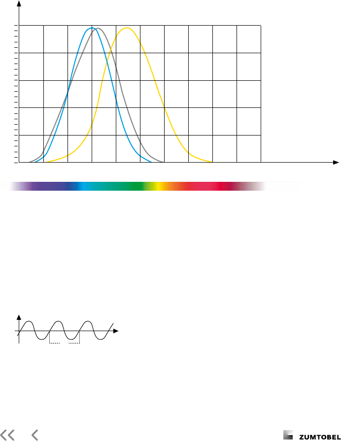
Relative spectral perception of brightness and melanopic eect
Wavelength [nm]
Eect as a percentage
What does the human eye see?
λ
Wavelength [nm]
Night
V'( )
λ
Day
V( )
λ
S
mel
( )
λ
Explanation of the three curves:
V(λ) Perception of brightness, daytime seeing with the cones
V'(λ) Night-time seeing with the rods
S
mel
(λ) Melatonin suppression with the photosensitive ganglion cells

The Lighting Handbook
Human Centric Lighting
Human Centric Lighting (HCL) expresses the positive eect of
light and lighting on the health, well-being and performance
of humans and thus has both short and long-term benets.
Light has a triple eect
Light for visual functions
– Illumination of task area in conformity
with relevant standards
– Glare-free and convenient
Light for emotional perception
– Lighting enhancing architecture
– Creating scenes and eects
Light creating biological eects
– Supporting people’s circadian rhythm
– Stimulating or relaxing
What is light?


The Lighting Handbook
Luminous ux – Luminous intensity – Illuminance – Luminance
Basic parameters used in lighting
Luminous ux Φ
Luminance L
Lumen [lm]
[lm/sr*m
²
][cd/m
²
]
Luminous intensity Ι Illuminance E
Candela [lm/sr][cd] Lux [lm/m
²
][lx]
Ω solid angle into which luminous ux is emitted
A area hit by luminous ux
A
L
· cos visible areas of light source
ρ reectance of area
.
* for diuse surface areas
Ι
Φ
Ω
E
Φ
A
L
Ι
A
L
· cos
L
E · ρ
*

The Lighting Handbook
Luminous ux
The luminous ux describes the quantity of light emitted
by a light source.
The luminous eciency is the ratio of the luminous ux
to the electrical power consumed (lm/W). It is a measure
of a light source’s economic eciency.
Luminous intensity
The luminous intensity describes the quantity of light that
is radiated in a parti cular direction. This is a useful measure-
ment for directive lighting elements such as reectors. It is
represented by the luminous inten sity distribu tion curve
(LDC).
Abbreviation: Φ Phi Unit: lm Lumen
Abbreviation: Ι Unit: cd Candela
Abbreviation: E Unit: lx Lux
Abbreviation: L Unit: cd/m
Illuminance
Illuminance describes the quantity of luminous ux falling on
a surface. Relevant standards specify the required illuminance
(e.g. EN “Lighting of indoor workplaces”).
Illuminance: E(lx)
luminous ux (lm)
area (m)
Luminance
Luminance is the only basic lighting para meter that is
perceived by the eye.
It describes on the one hand a light source’s impression of
brightness, and on the other, a surface and therefore depends to
a large extent on the degree of reection (colour and surface).

The Lighting Handbook
The right light – traditional and new quality criteria
Illuminance – denition of terminology
Traditional quality criteria
– Sucient illumination level
– Harmonious brightness distribution
– Glare limitation
– Avoidance of reections
– Good modelling
– Correct light colour
– Appropriate colour rendering
Illuminance maintenance value Ē
m
Value below which the illuminance level must
not fall in the visual task area.
Visual task area
Illuminance levels are specied for specic
visual tasks and are designed for the area in
which these may take place.
If the exact location is unknown, the room
as a whole or a dened area of the work-
station is used for specication.
The visual task area may be a horizontal,
vertical or inclined plane.
Area immediately surrounding the visual
task area
Here illuminance may be one level lower than
in the visual task area (e.g. lx to lx).
New quality criteria
– Changing lighting situations
– Personal control
– Energy eciency
– Daylight integration
– Light as an interior design element
Maintenance factor
The initial value multiplied by the mainte-
nance factor gives the illuminance
maintenance value.
The maintenance factor can be determined
individually, and takes the installation’s
reduction in luminous ux caused by soiling
and ageing of lamps, luminaires and room
surfaces into account.
The maintenance schedule (the cleaning
and maintenance intervals for the lamps and
installation) must be documented.
See also Section – Checklists.
Uniformity U
O
In order to perform visual tasks in illuminated
areas, there should not be any great dier-
ences in brightness so that uniformity should
not fall below U
O
E
min
/Ē.
Quality characteristics of lighting

The Lighting Handbook
Maintenance value maintenance factor x initial value
Relative illuminance (%)
Operating time
(years)
– Initial value
– Maintained
illuminance with
-year cleaning
– System value with-
out maintenance
Reectance factors
The reectance factors of the room and
object surfaces determine not only the
perception of the room but also the reected
light and thus the room’s brightness.
The reectance factor table in the system
helps you determine the reectance factors.

The Lighting Handbook
Glare – glare limitation
Direct glare
Reected glare
Cause
– Luminaires without glare control
– Very bright surfaces
Eect
– Loss of concentration
– More frequent mistakes
– Fatigue
Remedy
– Luminaires with limited luminance levels
– Blinds on windows
Cause
– Reective surfaces
– Incorrect luminaire arrangement
– Incorrect workstation position
Eect
– Loss of concentration
– More frequent mistakes
– Fatigue
Remedy
– Matching luminaire to workstation (layout)
– Indirect lighting
– Matt surfaces
Quality characteristics of lighting
The evaluation of glare
The glare of all luminaires that are in the
room regularly can be evaluated with the
UGR method, as specied in the standard
EN- “Lighting of indoor workplaces”.
However LED luminaires with very bright
light points, which can be perceived indi-
vidually, are crucial.
Classic VDU workstation luminaires
The standard requires the luminance of the
luminaire to be below or cd/m at
an angle of °.

The Lighting Handbook
UGR = 8 log
,
L
b
∑
LΩ
(1) (2)
The UGR method
The standardised UGR method (unied glare
rating) is used to assess (psychological) glare.
The UGR value is calculated with a formula.
This takes into account all of the luminaires
in the system that contribute to the impres-
sion of glare. The UGR values for luminaires
are determined using the table method
pursuant to CIE . Zumtobel quotes both a
UGR reference value for a reference room
and the UGR tables for other room sizes for
the majority of luminaires in its data sheets
and on their website.
The UGR tables are available for each lumi-
naire via the respective photometric data
sheet: Select a product Photometry
Select a layout
The values are hereby used for a classica-
tion on a glare level. A comparison of indi-
vidual values does not allow any statement.
Example: . is (level) but not better
than . (same glare level ).
Note: the glare value R
G
is used outdoors.
It is explained in the standard EN -.
The UGR method takes account of the
brightness of walls and ceilings () as well as
all luminaires in the system that contribute to
the sensation of glare (). The result is a
UGR index.
The UGR limits are specied in the
EN standard for activities and visual
tasks (see tables on pages –).
UGR limits (UGR
L
) that must not be
exceeded:
Technical drawing
Reading, writing, training, meetings,
computer-based work
Craft and light industries
Heavy industry
Railway platforms, foyers
( )
P

The Lighting Handbook
The luminance limit curve method assesses
the mean luminance of a luminaire from a
viewing angle of ° to °.
The new European standard sets UGR
as the maximum permissible value for
oces, which is equivalent to the luminance
limiting curve for lx in Quality class .
The limit value method was used in the
former standard DIN to assess the glare.
Quality characteristics of lighting
A
a
h
s
Luminance L in cd/m
Quality class
A
for nominal illuminance (lx)
UGR
L
°
°
°
°
°
°
°

The Lighting Handbook
Illuminance levels on ceilings
and walls
Spatial illumination
Unlit ceilings and walls create an unpleasant
room impression. Bright surfaces, however,
pleasantly enhance the room climate.
The EN standard therefore
requires an illuminance level of at least lx
or lx* on ceilings and at least lx or
lx* on walls. In fact, these levels ought to
be sig nicantly exceeded and should be at
least lx on walls.
* in oces, class rooms, hospitals
In order to enhance people’s and objects’
recognisability in a room, basic requirements
are placed on cylindrical illuminance Ē
Z
and
modelling.
Hence, Ē
Z
should be as high as lx in
rooms used for communication.
Modelling is the ratio between cylindrical
and horizontal illuminance at a specic point
and should be between . and ..
Ē
Z

The Lighting Handbook
Light colour
Colour rendering
The light colour describes the colour
appearance of the light.
In addition to the colours of the surfaces, it is also the
light colour that determines a room’s basic atmosphere!
Please refer to Chapter – Technology for light colours of
light sources and changes to the light colour.
Colour rendering is the ability of a light
source to reproduce surface colours
( test colours R
to R
) as faithfully as
possible compared to a reference light
source. It is identied by the colour rendering
index (CRI). The best colour rendering is
R
a
.
Light sources are divided up into colour
rendering levels:
R
a
very good colour rendering
R
a
good colour rendering
Colour rendering of less than should not
be selected at workplaces.
If light sources with a colour rendering
index below are used in exceptional cases,
it has to be ensured that safety colours can
be recognised without any problems.
The saturated test colours R
to R
are
also used occasionally to describe special
functions of a light source. The reproduction
of these colours is then quoted separately.
Colour temperature Appearance Association
ww (warm white) up to K reddish warm
nw (intermediate white) – K white neutral
tw (cool white) from K bluish cool
Light
R
greyish red
Dark
R
greyish yellow
Strong
R
yellow green
Moderate
R
yellowish green
Light
R
blueish green
R
Light blue
R
Light violet
Light
R
reddish purple
R
Strong red
R
Strong yellow
R
Strong green
R
Strong blue
Light
R
yellowish pink
Moderate
R
olive green (leaf)
Quality characteristics of lighting

The Lighting Handbook
The Mean illuminance is the arithmetic
brilliance level measured with a luxmeter
in a dened grid, under precisely specied
conditions.
Measuring illuminance
Measuring instruments:
Description and precision
– L: maximum precision, tolerance
– A: high precision, tolerance
– B: average precision; tolerance
(minimum requirement)
Measuring conditions
– Avoid external light/daylight
(measure separately and subtract)
– Check mains voltage and ambient
temperature
– Use new, burnt-in lamps (discharge
lamps h)
Measuring grid and measuring level
In order to facilitate inspection of the light-
ing system, the measuring grid has been
specied in the EN (Lighting of work-
places) and EN (Lighting of sports
facilities) standards.
The following recommendations apply for the
height of the measuring levels:
– Workplaces . m;
sports facilities (oor) . m
– Circulation areas, stairs,
car parks (oor) . m
– Cylindrical illuminance . m
– Measuring grid: congruent triangles
– Measuring grid not congruent with
luminaire layout grid
Size of measuring eld Grid element spacing
m . m
m . m
m m
m m
m m

The Lighting Handbook
The following aspects have to be taken into account for the
illumination of squares and parks, buildings and facades:
– targeted illumination of the areas to be visualised,
both horizontal and vertical
– creation of a three-dimensional perception of the room
through dierent brightness levels and shades
– balanced brightness distribution
– avoidance of strong dark-light contrasts
– limitation of the glare eect for residents and passers-by
– choose matching light colour and colour rendering
– no unused stray light
– when illuminating horizontal areas:
no light emission in the upper half of the room
Darkness has to be respected at night.
Outdoor lighting

The Lighting Handbook
In order to restrict the interfering eect, EN - species the luminous
intensities and luminances quoted in the table for outdoor spaces:
Maximum permissible interference eects of outdoor lighting systems
E Dark areas such as national parks or protected places
E Areas with little local brightness, such as industrial or residential areas in rural surroundings
E Areas with moderate local brightness, such as industrial or residential areas in suburbs
E Areas of high local brightness, such as city centres and commercial centres
E
v
is the maximum vertical luminous intensity at the place of immission in lx
I is the luminous intensity of each individual light source in the potential direction of interference in cd
R
UL
is the share of the light output of the luminaire(s) radiated above the horizontal plane with the luminaire(s)
in its/their installed position and location in
L
b
is the highest mean luminance of a building’s facade in cd/m
L
s
is the highest mean luminance of signs in cd/m
* In the event that there is no enforcement time, the higher values may not be exceeded and the lower
values should preferably be taken as limit values
Environ-
mental
zone
Li
ght at the place
of immission
Luminous intensity
of the luminaire
Share
of light
pointing
upwa
rds
Luminance
E
v
I R
UL
L
b
L
s
lx cd cd/m cd/m
before enforce-
ment time*
aft
er enforce-
ment time
before enforce-
ment time*
after enforce-
ment time
Building
facade Signs
E
E
E
E

The Lighting Handbook
Types of lighting
– Light falls from the luminaires on the
ceiling directly onto the workplace, in part
highly directional
– Glare suppression is important under
at angles
– The ceiling can appear dark (cave eect)
– The workplace layout should not allow
any shadows
– High energy eciency is achieved for the
work area
– Light is directed to the ceiling and walls so
that it illuminates the workplaces indirectly
– The lighting eect may appear diuse
through the absence of shadows
– The room increases in height
– The light is glare-free
– Workplaces can be arranged at random
– Lower energy eciency
Direct lighting
Indirect lighting

The Lighting Handbook
– Light is directed to the workplace directly
and indirectly via the ceiling from
suspend ed luminaires or free-standing
luminaires
– Pleasant room visuals
– High user acceptance
– Good contrast ratios
– Flexible workplace layout with an indirect
share of
– Good combination of energy eciency
and lighting quality
– The advantages of direct-indirect lighting
are combined in a ceiling-mounted
luminaire
– Possibility of a free workplace layout
– Glare-free lighting that looks good
make for a high acceptance
– Gives impression of daylight in a room
– Good combination of energy eciency
and lighting quality
Indirect/direct lighting
Mellow Light

The Lighting Handbook
The denition of individual visual tasks for
the purpose of lighting design in a room,
as provided for in the EN standard,
opens up new perspectives for lighting
design. The quantity and quality of light can
now be specied exactly for any task area.
Task area related lighting concepts are a
customised tool to fully exploit the additional
options provided. At the same time they
oer nancial scope that can be used to
impro ve lighting comfort and enhance the
eect of a room.
Lighting concepts
Room-related lighting concepts take neither individual task areas nor
dierent visual tasks into account. They are based on the most demand-
ing task performed in the room. The position of the workstation is not
dened, the entire room disposes of a uniform lighting quality.


The Lighting Handbook
Energy eciency in buildings
The energy requirement of the lighting is
also determined when issuing an energy
performance certicate pursuant to the
European Energy Performance of Buildings
Directive.
The LENI (Lighting Energy Numeric
Indicator) stands for the actual energy
consumption of a lighting system in kWh per
square metre and year.
The LENI is determined in accordance with
the specications of the EN standard
(Energy performance of buildings – Energy
requirements for lighting).
Formula for calculating a lighting installation’s
energy consumption
LENI =
[kWh/(m² year)]
∑
(P
n
x F
C
) x {(t
D
x F
O
x F
D
) + (t
N
x F
O
)}
A
Without elaborating on individual parameters in greater
detail, the following relevant factors are identied:
– The installed load (P
n
)
– Multiplied by the annual hours of use by day (t
D
) and
at night (t
N
)
– Reduced by the factors ( ) for daylight-based control (F
D
),
presence-based control(F
O
) and a constant lighting control
system (F
C
) (e.g. maintenance control)
– The area assessed (A)
LENI also takes charging energy for emergency lighting and
standby energy into account.

The Lighting Handbook
The following factors have a positive impact on the
reduction of energy consumption
– Sensible control of lighting
– Use of daylight
– Use of presence detectors
– Intelligent consideration of hours of use
– Energy-ecient lamps
– Need-based use of luminaires and lighting solutions,
specied for the respective application
– Constant lighting control (maintenance control)

The Lighting Handbook
Chapter
Standard values for indoor and outdoor lighting
Standard values for lighting of indoor and outdoor workplaces
and sports facility lighting
Indoor workplaces
Trac zones and general areas inside buildings
Industrial activities and crafts
Oces
Retail premises
Places of public assembly
Educational premises
Health care premises
Transportational areas
Sports facilities
Outdoor workplaces
General circulation areas
Airports
Building sites
Fuel filling service stations
Industrial sites and storage areas
Offshore facilities for gas and oil extraction
Parking areas
Petrochemical and other hazardous industries
Power, electricity, gas and heat plants
Railway and tramways
Saw mills
The Lighting Handbook
Standard values for lighting of indoor and outdoor workplaces
and sports facility lighting
Tables and gures were taken from the
European standards.
“Lighting of indoor workplaces”,
EN12464-1
(June )
“Lighting of outdoor workplaces”,
EN12464-2
(October )
“Sports facility lighting”, EN 12193
(April )
The following limits have been specied in
the tables:
Illuminance levels must not fall below
the Ē
m
maintenance values in the visual
task area. If the precise location is not
known, the limit should be applied to the
whole room or a specic working area.
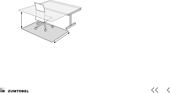
Example for an oce task area:
The maintenance factors can be deter-
mined on a case-by-case basis, according
to the manufacturer’s specications.
Where no individual maintenance data is
available, the following values are recom-
mended as reference maintenance factors for
modern technology and three-yearly mainte-
nance: . in a clean atmosphere, and . in
very dirty environments.
EN species that the lighting
designer must document the maintenance
factor and maintenance schedule.
UGR
L
is the upper limit for direct glare. The
UGR value calculated in the design process
must lie below this.
Uniformity U
O
is the ratio between the
lowest (E
min
) and the mean illuminance level
(Ē) in the area to be evaluated. The result is
a minimum level.
R
a
is the lower limit for the colour rendering
index. The R
a
of the selected lamp must be
equal to or greater than this value.
height = 0.7
5 m
task area
user oor-area
1.00 m

The Lighting Handbook
Type of interior, task or activity
Trac zones and general areas inside buildings Ē
m
UGR
L
U
O
R
a
Circulation areas within buildings Circulation areas and corridors .
Stairs, escalators, moving walkways .
Elevators, lifts .
Loading ramps/bays .
Rest, sanitation and
rst aid rooms
Cant
eens, pantries .
Rest rooms .
Rooms for physical exercise .
Cloakrooms, washrooms, bathrooms, toilets .
Sick bays .
Rooms for medical attention .
Control rooms Plant rooms, switch gear rooms .
Telex, post room, switchboard .
Store rooms, cold stores Store and stockrooms .
Dispatch packing handling areas .
Storage rack areas Gangways: unmanned – .
Gangways: manned .
Control stations .
Front of (high-bay) racks – .
Industrial activities and crafts
Agriculture Loading and operating of goods, handling equipment
and machinery .
Bu
ildings for livestock – .
Sick animal pens; calving stalls .
Feed preparation; dairy; utensil washing .
Bakeries Preparation and baking .
Finishing, glazing, decorating .
Cement, cement goods,
concrete, bricks
Dry
ing .
Preparation of materials; work on kilns and mixers .
General machine work .
Rough forms .
Ceramics, tiles, glass, glassware Drying .
Preparation, general machine work .
Enamelling, rolling, pressing, shaping simple parts,
glazing, glass blowing .
G
rinding, engraving, glass polishing, shaping precision
parts, manufacture of glass instruments .
Grinding of optical glass, crystal, hand grinding
and engraving .
P
recision work e.g. decorative grinding, hand painting .
Manufacture of synthetic precious stones .

The Lighting Handbook
Indoor workplaces
Type of interior, task or activity
Industrial activities and crafts Ē
m
UGR
L
U
O
R
a
Chemical, plastics and
rubber industry
Rem
ote-operated processing installations – .
Processing installations with limited manual intervention .
Constantly manned work places in processing installations .
Precision measuring rooms, laboratories .
Pharmaceutical production .
Tyre production .
Colour inspection .
Cutting, nishing, inspection .
Electrical industry Cable and wire manufacture .
Winding:
– large coils .
– medium-sized coils .
– small coils .
Coil impregnating .
Galvanising .
Assembly work:
– rough e.g. large transformers .
– medium e.g. switchboards .
– ne e.g. telephones, radios, IT products (computers) .
– precision e.g. measuring equipment,
printed circuit boards
.
Electronic workshops, testing, adjusting .
Food stus and luxury
food industry
Wor
k places and zones in:
– breweries, malting oors
– for washing, barrel lling, cleaning, sieving, peeling
– cooking in preserve and chocolate factories
– work places and zones in sugar factories
– for drying and fermenting raw tobacco, fermentation .
Sorting and washing of products, milling, mixing, packing .
Work places and critical zones in slaughter houses, butch
-
ers, dairies mills, on ltering oor in sugar reneries
.
Cutting and sorting of fruit and vegetables .
Manufacture of delicatessen foods, kitchen work,
manufacture of cigars and cigarettes
.
Inspection of glasses and bottles, product control,
trimming, sorting, decoration
.
Laboratories .
Colour inspection .

The Lighting Handbook
Type of interior, task or activity
Industrial activities and crafts Ē
m
UGR
L
U
O
R
a
Foundries and metal casting Man-size underoor tunnels, cellars, etc. – .
Platforms .
Sand preparation .
Dressing rooms .
Workstations at cupola furnaces and mixers .
Casting bays .
Shake out areas .
Machine moulding .
Hand and core moulding .
Die casting .
Model building .
Hairdressers Hairdressing .
Jewellery manufacturing Working with precious stones .
Manufacture of jewellery .
Watch making (manual) .
Watch making (automatic) .
Laundries and dry cleaning Goods in, marking and sorting .
Washing and dry cleaning .
Ironing, pressing .
Inspection and repairs .
Leather and leather goods Work on vats, barrels, pits .
Fleshing, skiving, rubbing, tumbling of skins .
Saddlery work, shoe manufacture: stitching, sewing,
polishing, shaping, cutting, punching
.
Sorting .
Leather dyeing (machine) .
Quality control .
Colour inspection .
Shoe making .
Glove making .
Metal working and processing Open die forging .
Drop forging .
Welding .
Rough and average machining: tolerances . mm .
Precision machining; grinding: tolerances . mm .
Scribing, inspection .
Wire and pipe drawing shops; cold forming .
Plate machining: thickness mm .
Sheet metalwork: thickness mm .
Tool making; cutting equipment manufacture .

The Lighting Handbook
Type of interior, task or activity
Indoor workplaces
Industrial activities and crafts Ē
m
UGR
L
U
O
R
a
Metal working and processing Assembly:
– rough .
– medium .
– ne .
– precision .
Galvanising .
Surface preparation and painting .
Tool, template and jig making, precision mechanics,
micromechanics
.
Paper and paper goods Edge runners, pulp mills .
Paper manufacture and processing, paper and
corrugating machines, cardboard manufacture .
S
tandard bookbinding work, e.g. folding, sorting,
glueing, cutting, embossing, sewing
.
Power stations Fuel supply plants – .
Boiler houses .
Machine halls .
Side rooms, e.g. pump rooms, condenser rooms etc.;
switchboards (inside buildings) .
Control rooms .
Printers Cutting, gilding, embossing, block engraving, work on
stones and platens, printing machines, matrix making .
Paper sorting and hand printing .
Type setting, retouching, lithography .
Colour inspection in multicoloured printing .
Steel and copper engraving .
Rolling mills, iron and steel works Production plants without manual operation – .
Production plants with occasional manual operation .
Production plants with continuous manual operation .
Slab storage facilities – .
Furnaces .
Mill trains; coilers; shear lines .
Control platforms; control panels .
Test, measurement and inspection .
Underoor man-sized tunnels; belt sections; cellars etc. – .
Textile manufacture and processing Work places and zones in baths, bale opening .
Carding, washing, ironing, devilling machine work,
drawing, combing, sizing, card cutting, pre-spinning,
jute and hemp spinning
.
Spinning, plying, reeling, winding .

The Lighting Handbook
Type of interior, task or activity
Industrial activities and crafts Ē
m
UGR
L
U
O
R
a
Textile manufacture and processing Warping, weaving, braiding, knitting .
Sewing, ne knitting, taking up stitches .
Manual design, drawing patterns .
Finishing, dyeing .
Drying room .
Automatic fabric printing .
Burling, picking, trimming .
Colour inspection; fabric control .
Invisible mending .
Hat manufacturing .
Vehicle construction and repair Body work and assembly .
Painting, spraying chamber, polishing chamber .
Painting: touch-up, inspection .
Upholstery manufacture (manned) .
Final inspection .
General vehicle servicing, repair and inspection .
Wood working and processing Automatic processing e.g. drying, plywood manufacturing .
Steam pits .
Saw frames .
Work at joiner’s bench, glueing, assembly .
Polishing, painting, fancy joinery .
Work on wood working machines e.g. turning, uting,
dressing, rebating, grooving, cutting, sawing, sinking .
Selection of veneer woods .
Marquetry, inlay work .
Quality control, inspection .

The Lighting Handbook
Type of interior, task or activity
Indoor workplaces
Oces Ē
m
UGR
L
U
O
R
a
Filing, copying, etc. .
Writing, typing, reading, data processing .
Technical drawing .
CAD work stations .
Conference and meeting rooms .
Reception desks .
Archives .
Retail premises
Sales areas .
Till areas .
Wrapper tables .
Places of public assembly
General areas Entrance halls .
Cloakrooms .
Lounges .
Ticket oces .
Restaurants and hotels Reception/cashier desks, porters desks .
Kitchens .
Restaurant, dining room, function room – – –
Self-service restaurants .
Buets .
Conference rooms .
Corridors .
Theatres, concert halls, cinemas Practice rooms .
Dressing rooms .
Seating areas – maintenance, cleaning .
Stage areas – construction .
Trade fairs, exhibition halls General lighting .
Museums Exhibits, insensitive to light according to
requirements
Light-sensitive exhibits
Libraries Bookshelves .
Reading areas .
Counters .
Public car parks (indoor) In/out ramps (during the day) .
In/out ramps (at night) .
Trac lanes .
Parking areas – .
Ticket oces .

The Lighting Handbook
Type of interior, task or activity
Educational premises Ē
m
UGR
L
U
O
R
a
Nursery school, play school Play rooms .
Nurseries .
Handicraft rooms .
Educational buildings Classrooms, tutorial rooms .
Classrooms for evening classes and adults education .
Lecture halls .
Black, green wallboards and whiteboards .
Demonstration tables .
Art rooms .
Art rooms in art schools .
Technical drawing rooms .
Practical rooms and laboratories .
Handicraft rooms .
Teaching workshops .
Music practice rooms .
Computer practice rooms (menu driven) .
Language laboratories .
Preparation rooms and workshops .
Entrance halls .
Circulation areas, corridors .
Stairs .
Student common rooms and assembly halls .
Teachers rooms .
Library: bookshelves .
Library: reading areas .
Stock rooms for teaching materials .
Sports halls, gymnasiums, swimming pools (general use) .
School canteens .
Kitchens .
Health care premises
Rooms for general use Waiting rooms .
Corridors: during the day .
Corridors: cleaning .
Corridors: during the night .
Multiple-use corridors .
Day rooms .
Elevators, lifts for passengers and visitors .
Service lifts .

The Lighting Handbook
Type of interior, task or activity
Indoor workplaces
Health care premises Ē
m
UGR
L
U
O
R
a
Sta rooms Sta oces .
Sta rooms .
Wards, maternity wards General lighting .
Reading lighting .
Simple examinations .
Examination and treatment .
Night lighting, observation lighting – –
Bathrooms and toilets for patients .
Examination rooms (general) General lighting .
Examination and treatment .
Eye examination rooms General lighting .
Examination of the outer eye – –
Reading and colour vision tests with vision charts .
Ear examination rooms General lighting .
Ear examination – –
Scanner rooms General lighting .
Scanners with image enhancers and television systems –
Delivery rooms General lighting .
Examination and treatment .
Treatment rooms (general) Dialysis .
Dermatology .
Endoscopy rooms .
Plaster rooms .
Medical baths .
Massage and radiotherapy .
Operating areas Pre-op and recovery rooms .
Operating theatres .
Operating cavity –
Intensive care units General lighting .
Simple examinations .
Examination and treatment .
Night watch –
Dentists General lighting .
At the patient – .
Operating cavity – – – –
White teeth matching – – – –
The Lighting Handbook
Type of interior, task or activity
Health care premises Ē
m
UGR
L
U
O
R
a
Laboratories and pharmacies General lighting .
Colour inspection .
Decontamination rooms Sterilisation rooms .
Disinfection rooms .
Autopsy rooms and mortuaries General lighting .
Autopsy tables and dissecting tables – –
Transportational areas
Airports Arrival and departure halls, baggage claim areas .
Connecting areas, escalators, travelators .
Information desks, check-in desks .
Customs and passport control desks .
Waiting areas .
Luggage store rooms .
Security check areas .
Air trac control towers .
Testing and repair hangars .
Engine test areas .
Measuring areas in hangars .
Railway installations Covered platforms and passenger subways (underpasses) – .
Fully enclosed platforms, large number of persons – .
Pedestrian underpasses, small number of persons .
Pedestrian underpasses, large number of persons .
Ticket halls and concourses .
Ticket and luggage oces and counters .
Waiting rooms .
Entrance halls, station halls – .
Signal boxes, technical rooms .
Access tunnels – .
Maintenance and repair bays .

The Lighting Handbook
Type of interior, task or activity
Indoor workplaces
The following details apply to competition class I (lower requirements apply to classes II and III)
Ē
m
and R
a
data according to European Standard EN
General school sports data from EN
An R
a
level of should be preferred
For lighting for training purposes, usually an UGR
L
level of should be observed
Sports facilities Ē
m
R
a
Aerobics
Archery
Athletics (all disciplines)
Badminton
Basketball
Billiards
Boccia
Boules
Bowling
Bowls
Boxing (competition/training) /
Climbing
Cricket
Cricket nets
Curling (target/playing areas) /
Cycling
Dancing (tness)
Darts
Fencing
Figure skating
Fistball
Floorball
Football (indoor)
Gymnastics
Gymnastics (oor exercises, apparatus work)
Handball
Hockey
Ice hockey
Ice speed skating ( m and skating rink)
Judo
Kendo/Karate
Netball
Ninepins

The Lighting Handbook
Type of interior, task or activity
Sports facilities Ē
m
R
a
Petanque
Racketball
Riding
Roller skating
Shooting
School sports
School sports (general use)
Snooker
Squash
Swimming
Swimming (school level)
Table tennis
Tennis
Volleyball
Weight lifting
Wrestling

The Lighting Handbook
Type of outdoor workplace, task or activity
Outdoor workplaces
General circulation areas at outdoor workplaces Ē
m
R
a
Walkways exclusively for pedestrians
Trac areas for slowly moving vehicles max. ( km/h),
e.g. bicycles, trucks and excavators
Re
gular vehicle trac (max. km/h)
Pedestrian passages, vehicle turning, loading and unloading points
Airports
Hangar aprons
Terminal aprons
Loading areas
Fuel depots
Aircraft maintenance stands
Building sites
Clearance, excavation and loading
Construction areas, drain pipes mounting, transport,
auxiliary and storage tasks
Fr
amework element mounting, light reinforcement work, wooden
mould and framework mounting, electric piping and cabling
Element jointing, demanding electrical, machine and
pipe mountings
Fu
el lling stations
Vehicle parking and storage areas
Entry and exit driveways: dark environment
(i.e. rural areas and suburbs)
Ent
ry and exit driveways: light environment (i.e. cities)
Air pressure and water checking points and other service areas
Meter reading areas
Industrial sites and storage areas
Short term handling of large units and raw materials,
loading and unloading of solid bulk goods
Con
tinuous handling of large units and raw materials, loading and
unloading of freight, lifting and descending location for cranes,
open loading platforms
Reading of addresses, covered loading platforms, use of tools,
ordinary reinforcement and casting tasks in concrete plants
D
emanding electrical, machine and piping installations, inspection

The Lighting Handbook
Type of outdoor workplace, task or activity
Oshore facilities for gas and oil extraction Ē
m
R
a
Sea surface below the platform
Ladders, stairs, walkways
Boat landing areas, transport areas
Helicopter landing areas
Drill towers
Processing areas
Piping depot/deck
Test stations, shakers, drillheads
Pump areas
Lifeboat areas
Drill oors, drill surfaces, platforms at drill tower
Sludge chambers, sampling
Crude oil pumps
Facility areas
Rotary tables
Parking areas
Light trac, e.g. parking areas of shops, terraced and
apartment houses; cycle parks
Med
ium trac, e.g. parking areas of department stores,
oce buildings, plants, sports and multipurpose building complexes
He
avy trac, e.g. parking areas of schools, churches, major shop-
ping centres, major sports and multipurpose building complexes
Pet
rochemical and other hazardous industries
Handling of servicing tools, utilisation of manually regulated valves,
starting and stopping motors, lighting of burners
Filling and emptying of container trucks and wagons with risk free
substances, inspection of leakage, piping and packing
Filling and emptying of container trucks and wagons with
dangerous substances, replacements of pump packing, general
service work, reading of instruments
Fu
el loading and unloading sites
Repair of machines and electric devices
Power, electricity, gas and heat plants
Pedestrian movements within electrically safe areas
Handling of servicing tools, coal
Overall inspection
General servicing work and reading of instruments
Wind tunnels: servicing and maintenance
Repair of electric devices

The Lighting Handbook
Type of outdoor workplace, task or activity
Outdoor workplaces
Railways and tramways Ē
m
R
a
Railway areas including light
railways, tramways, monorails,
miniature rails, metro, etc.
Tra
cks in passenger station areas, including stabling
Railway yards: at marshalling, retarder and classication yards
Hump areas
Freight track, short duration operations
Open platforms, rural and local trains, small number of passengers
Walkways
Level crossings
Open platforms, suburban and regional trains with large number of
passengers or inter-city services with small number of passengers
Freight track, continuous operation
Open platforms in freight areas
Servicing trains and locomotives
Railway yards handling areas
Coupling areas
Stairs, small and medium-size stations
Open platforms, inter-city services
Covered platforms, suburban or regional trains or inter-city services
with small number of passengers
Covered platforms in freight areas, short duration operations
Covered platforms, inter-city services
Stairs, large stations
Covered platforms in freight areas, continuous operation
Inspection pit
Saw mills
Timber handling on land and in water, sawdust and chip conveyors
Sorting of timber on land or in water, timber unloading points
and sawn timber loading points, mechanical lifting to timber
conveyor, stacking
Re
ading of addresses and markings of sawn timber
Grading and packaging
Feeding into stripping and chopping machines

The Lighting Handbook
Extracts from:
ÖNORM [Austrian standard] EN -
Light and lighting – Lighting of workplaces – Part :
indoor workplaces (--)
ÖNORM EN Part -,
Light and lighting – Lighting of workplaces – Part :
outdoor workplaces (--)
ÖNORM EN
Light and lighting – Sports facility lighting (--)
Published with permission by the Austrian Standards Institute,
A- Vienna, Heinestrasse
For ordering standards and products or research on the subject,
please go to www.on-norm.at
Pay attention to the EN series of standards for
street lighting.

The Lighting Handbook
Chapter
Lighting application
Active Light | Connecting with Nature
Creating Light creates Life
Active Light in connection with art and nature
Application areas
Light for Oces and Communication
Light for Education and Science
Light for Presentation and Retail
Light for Hotel and Wellness
Light for Art and Culture
Light for Health and Care
Light for Industry and Engineering
Light for Outdoor and Architecture
Light for Living

The Lighting Handbook
01:00 02:00 03:00 04:00 05:00 06:00 07:00 08:00 09:00 10:00 11:00 12:00
Active Light | Connecting with Nature
Creating Light creates Life
Always reliable yet simultaneously surprising, natural light
has guided and accompanied us since the dawn of time. It is
intuitive to our needs and caters to our natural rhythm. It has
a dynamic inuence on our sight, thus blessing us with new
images every day that set our emotions free. It controls
human processes and inuences our internal clock.
Active Light emulates natural light in a unique way, which,
when unied with architecture, opens the realms of time and
space to various ambiances of human interaction.
Consequently, an exploration in light ow, intensity, color and
focus points are created to achieve what natural light can:
evoking emotion through light.


The Lighting Handbook
Active Light in connection with art and nature
Only through light can art truly become an experience. The
perfect presentation of paintings, photographs, sculptures
and archaeological artefacts requires a deep understanding of
the respective space, the medium and the curatorial theme.
Eective lighting concepts follow the planning principles of
museum lighting. A successful lighting design will encompass
the four dimensions of light – direction, illuminance, colour
and time – to create a fascinating single entity.
Active Light – Connecting with Nature
The four dimensions of light

The Lighting Handbook
Light for Oces and Communication
Working and feeling at ease
Making work easier – Complying with standards (adjusting illuminance levels to tasks)
– Avoiding glare by light
Creating an identity – Lighting design in the overall architectural context
– Taking CI into account
Promoting health – Adjusting biologically eective light to the circadian
day/night rhythm
– Daylight as preferred source of light
– Articial lighting using Tunable White
Employees as a cost factor – Sta cost analysis in comparison with investment and
operating costs
– Result: lighting solutions must be subject to people’s demands
– Light enhances people’s performance and creativity
Technology and exibility
Creating dierent zones – Structuring and orientation in space through lighting design for
vertical surfaces, transit areas, pools of light etc.
– Arranging groups using lighting management
Bolstering activity – Adjustment through lighting management
– Taking into account changing work media (such as tablets):
no high luminance levels at steep angles
Preserving individuality – Keeping demographic trends in mind
– Lighting management for individual control options
Being exible – Glare limitation at all angles for exible utilisation of space
– Lighting management: free-standing luminaire concepts and
re-grouping of ceiling solutions
Application areas

The Lighting Handbook
Eectiveness and eciency
Sustainability – Increases the value of buildings
– Lighting management:
daylight-based control or presence-based control
– Ecient luminaires, lighting concepts
Integral approach – All visual tasks and zones of the building
– Integrating the lighting management system into higher-level
building services
Rational refurbishment – Short payback periods of new technologies
– Wireless control technology
Added value thanks to LEDs – Perfect integration into lighting management system
– Unaected by frequent switching and dimming
– Life-cycle assessment shows benets: reduced energy consumption,
long service life, low maintenance eort
The requirements on lighting change over
time, and with the place, the person and
work they have to do. A lighting management
system is based on actual needs and provides
the optimum light.
Concentrated work and increasing commu-
nication place changing demands on the
lighting situation. Additional, biologically
eective components of articial lighting that
complement daylight at appropriate times of
day work in harmony with our internal body
clock and are invigorating.
Using time-based management, daylight-
based control and presence-based control,
the system achieves a high level of automa-
tion. This is associated with maximum energy
savings and exibility for adjustments.
Where sta members can individually
control the lighting situation in their work
environment, the technology is accepted
most easily. This requires sucient control
options and small groups of luminaires with
appropriately allocated responsibilities.
Customer benets of lighting management and Active Light

The Lighting Handbook
Light for Education and Science
Environmental aspects
Use of daylight – Energy eciency through lighting management
Ecient luminaires and
intelligent control
– LED solutions are highly ecient
– Frequent dimming and switching does not aect the
LEDs’ service life
Ergonomic compatibility
Performance and concentration – Standards cover basic visual requirements such as glare or
illuminance
– Emotional components enhance concentration
– Open room ambience thanks to brightening up of ceiling and walls
Feeling at ease and health – Feeling at ease enhances people’s performance
– Light stabilises the inner biological clock, measurably stimulates
hormonal processes
– Medical evidence shows that light enhances cognitive performance
Adjusting light to activities and
visual tasks
– Blackboard lighting: high visual demands because of accommodation
required from the eye for close and distant vision when reading and
copying from the blackboard
– Teamwork
Application areas

The Lighting Handbook
New teaching methods
Mobility and communication – Flexible seating arrangement
– More teamwork and communication
– Face recognition requires well-balanced direct/indirect components
– Quickly retrievable, exible luminaire grouping and scenes
– Presence-based control in case of extensive periods of use
(such as corridor zones at universities in the evening)
New learning methods and
teaching materials
– Increasingly screen-based work, also on tablets:
glare control at at and steep angles
New technologies
Variety and exibility – Lighting management: exible use of rooms, dynamically changing
light (daylight and articial lighting) creates variety
Lighting scenes at the touch
of a button
– Clearly laid out control units with selection of scenes
New teaching methods and media technolo-
gies require exible room usage and frequent
adjustment of lighting situations. These can
be implemented by the press of a button
using intuiti ve control units with predened
scenes – for working in small groups or
teacher-centred teaching, a reduced level
for data projector presentations or higher
vertical illuminance levels for blackboard and
ip charts.
Daylight is stimulating and enhances
people’s sense of well-being and perfor-
mance. Using daylight-based control and
presence-based control, maximum energy
savings are achieved – without any com-
promises in terms of lighting quality.
Blinds control enhances the contrasts for
presentation media and additionally increases
room comfort, since glare and thermal output
are minimis ed.
Customer benets of lighting management and Active Light

The Lighting Handbook
Light for Presentation and Retail
Setting the scene
Limbic Lighting – Target group-specic lighting solutions that aect the emotional
conditions of the customer groups
– Increase turnover by taking into account specic customer needs
at the POS
Stimulating desires – Guiding perception: direction of light, luminance levels
and light colours rich in contrast matched to the goods on display
Brand communication – Emotional lighting design through illumination of façades and shop
windows
Authenticity
Creating accents – High-precision accent lighting
– Excellent colour rendering: brilliance and authenticity
Directing the gaze – Long-distance eect, orientation and enhanced room depth
perception thanks to illuminated peripheral areas, vertical surfaces
and shelf rear walls
Reducing lighting distances – Presenting objects in greater detail
– Miniaturised lighting systems focus people’s attention on the
goods displayed
Modelling objects – Diuse light to lend sleek lines to highly reective objects
– Presenting objects authentically with a three-dimensional eect:
interplay of diuse and directed light
Application areas

The Lighting Handbook
Naturalness
Emphasising freshness – LED solutions with high colour rendering and matching
colour temperature
– Gentle illumination of fresh goods to boost sales
Adjusting colour temperature – LED incorporating revolutionary Tunable Food and
tunableWhite technology
– Choice of various colour temperatures in one luminaire
– Formerly: lters and lamps had to be changed
Gentle illumination – LED is virtually free from IR and UV radiation
– No lters or protective devices
Sustainability
Increasing eciency – Linear LED solutions instead of uorescent lamps
– Vertical luminance levels prevail over horizontal lighting design
Reducing energy consumption – LED combined with lighting management
– Monitoring ancillary areas via presence detectors
Replacing the lighting system – Comparing operating costs against investment costs
– Increased lighting quality with higher eciency possible
(LED technology)
Lighting scenes are adjusted to various activi-
ties using intuitive control points – from task
lighting at the POS terminals to gentle colour
changes required for the lounge.
Thanks to increasing energy awareness,
more and more dimmable luminaires are
used in retail spaces. Positive material
eects of goods and architecture are lever-
aged by possible changes in colour tem-
perature combined with luminance levels
(tunableWhite).
Skilfully controlled lighting solutions are
characterised by high levels of comfort and
exibility as well as low maintenance eort.
For example, perfect adjustment of the
light spectrum to the illuminated object is
achieved without complicated replacement of
lters. Using adequate control points, time-
lines or daylight-based control, ambient light-
ing is gently modied. The use of daylight not
only helps to save energy, but makes room
zones appear especially attrac tive.
Highly emotional illumination of goods and
surprise eects can be achieved using static
and dynamic lighting scenes.
Active Light solutions on the basis of
Limbic Lighting knowledge allow a dynamic
adaptation to the personality-based needs of
various target groups.
Customer benets of lighting management and Active Light

The Lighting Handbook
Light for Hotel and Wellness
New technologies
Networking – Lighting management system
– Lighting scenes: multi-functional use of seminar rooms and
conference halls
Flexible use of screens – Glare control at steep angles for smartphones and tablets
Exacting design aspirations
Enhancing architecture – Illumination of façade and entrance area
– Choice of luminaires reecting the hotel’s design language
Decorative luminaires – New designs thanks to LED technology
Attractive control units – Specially designed control units with intuitive lighting scenes
and pictographs for hotels
Globalisation
Variety of options – Extensive product portfolio
– Taking regional inuences into account
Service on site and multi-cultural
competence
– Global planning
– Transnational distribution network
– Regional adaptation
– Knowledge of national regulations
Application areas

The Lighting Handbook
Responsibility
Sustainable products – Environmentally certied luminaires
Ecient luminaires and opti mised
lighting management
– Sucient control options and central “o” of the entire unit next
to the room door
Safety and security – Integration of emergency lighting
– Orientation in corridors and car parks
Spa and wellness
Enhancing health and
well-being,
relaxation
– Gentle and dynamic changes in light colour
– Creating specic pools of light and dark zones in the spa area
When it comes to hotel rooms, the guest’s
individual wishes have top priority. In terms
of lighting, intuitive control units allow to
create personal settings: using blinds control,
articial lighting and daylight can be conveni-
ently adjusted to a variety of room require-
ments and visual demands – depending on
whether the guest wants to watch TV, put on
make-up or read.
Dynamic lighting scenes, exibly dened
via timelines or controlled according to
weather situation and time of day, have an
inuence on the guests’ well-being – mainly
in restaurants and wellness areas. Moreover,
they optimise the adaptation conditions for
the eye when entering the building, depend-
ing on the lighting situation outdoors, which
provides security and orientation.
Predened lighting scenes in conference
areas allow for multiple changes in media,
providing the right light at the press of a but-
ton. Integration of emergency lighting into
the higher-level lighting management system
allows central monitoring of the system.
Customer benets of lighting management and Active Light

The Lighting Handbook
Light for Art and Culture
Perfectly staged
Four dimensions of light – Experience art with Active Light that controls and compares
the light direction, luminous intensity, light colour and time
Art and architecture – Architectural and artistic confrontation to enhance the
experience of art
Lighting tools for a variety of planning approaches
Art-centred highlighting – Extensive portfolio for planning lighting, from Superspot to
Wallwasher
– Curatorial freedom through a variety of accessories along with
maximum exibility and precision
tunableWhite – Adjust the light colour in the context of the history of the work of art
(candlelight, daylight) curatorial context
– Change the light colour in the general lighting according to the
expectations of people and in the natural course of the day
architectural context
Application areas

The Lighting Handbook
A lighting management system makes sure
that exhibits which are sensitive to light are
exposed only to the amount of light that is
absolutely necessary: exactly that luminance
level or light colour (tunableWhite) that are
required for good perception. Thanks to
presence-based control, illumination is
restrict ed to the time when visitors are
present.
Times for switching on and o can be
specied for particular times of day. Blinds
management and daylight sensors allow just
the amount of daylight that is absolutely
necessary – as a balance between architec-
ture, human well-being, gentle illumination of
exhi bits and energy costs.
Unobtrusively and with central monitoring,
the emergency lighting system is integrated
into the lighting management system,
ensuring reliable visual conditions in an
emergency.
Conservation goals
Gentle LED technology – Marginal IR and UV load thanks to an LED product portfolio
Lighting management and
tunableWhite
– tunableWhite and lighting control to reduce potential damage
through shorter radiation times and the use of gentle wavelengths
Scientic support and advice – Service through on-site measurements and advice based on
scientic knowledge
Energy and maintenance
Energy costs – Short payback times through the use of new LED technology with
a lower energy consumption
– Dimmable luminaires are more gentle and optimise the
energy balance
Maintenance costs – Long service life of LED luminaires minimise the maintenance costs
– year warranty
Customer benets of lighting management and Active Light

The Lighting Handbook
Light for Health and Care
Health and activity
Quality for patients and persons
in need of care
– Taking into account dementia patients
– Avoiding mirror eects and reections (delusions)
Feeling at ease and supporting
the inner clock
– In many healthcare facilities, no daylight – an important means
of stabilising the inner clock – is available
– Little time is spent outdoors
– Compensation by articial lighting: well-adjusted changes in
light colours and illuminance levels
– High intensity in pools of light
Enhancing comfort and
providing security
– Bedside lighting
– Age-appropriate lighting scene concept in line with healthcare
requirements
Reliability and functionality
Visual comfort and security for
patients and residents
– Emergency lighting
– Providing orientation
– Avoiding heavy shadows and dark zones
– Pleasant corridor design using indirect light components on
ceiling and walls
Supporting diagnosis and
treatment
– Increase in illuminance levels: at the press of a button at the
patient’s bedside or via additional light components
– High colour rendering index
Optimising doctors’ and nurses’
working conditions
– Individual settings, intuitive operation
– Special illumination to meet high demands (operating theatres
and intensive-care units)
– Where people work at night: support the circadian rhythm with
biologically eective lighting
Flexibility – Modular lighting design so that the light can easily be adjusted to
the way the room is used
Application areas

The Lighting Handbook
Eco-friendly and economically ecient
Added value for operators
and investors
– Daylight-based control and lighting scenes that can be called up
individually enhance comfort and increase ecien cy
Optimising energy consumption – Ecient luminaires and light sources
– Corridor lighting with presence-based control and LED –
unaected by frequent switching and dimming
Enhancing the health and care
facility’s image
– High-quality appearance of façade, parking spaces,
entrance and waiting areas
Integral approach – Central lighting control system with monitoring, including the
emergency lighting system
Successful lighting solutions in residential
care homes and hospitals oer intuitive
age-appropriate control options that are also
suitable for use by disabled persons. Using a
lighting management system, a variety of
lighting scenes required for residential and
nursing purposes can be called up at the
press of a button.
Due to age-related changes in the eye, the
demand for light increases with age. For
more sophisticated visual tasks, the articial
lighting can be individually adjusted by
nursing sta and patients. As a result of
process es of degradation in the eye, biologi-
cally highly eective bluish components are
ltered out. The inner clock and the associ-
ated sleeping and resting patterns must
therefore be supported by spending time
outdoors or by biologically eective articial
lighting with high intensity levels or with a
large bluish component at dened times of
the day.
Timelines dened within the scope of the
lighting management system make the inter-
play of articial lighting and daylight perfect
at any time of day.
Customer benets of lighting management and Active Light

The Lighting Handbook
Light for Industry and Engineering
Eciency
Reducing energy consumption
and CO
emissions
– Up to working hours, often with little daylight, require highly
ecient technologies
– Primarily use of daylight, also to enhance well-being
– Presence-based monitoring of ancillary or less frequented areas
– Positioning companies as environmentally committed
by obtaining certicates
Facilitating maintenance and
replacing the lighting system
– Large-scale room dimensions result in high maintenance eort
– Reduced eort thanks to durable and ecient LED solutions and
lighting management systems
Adaptability
Variety of options for rooms
with high ceilings
– Uniform general lighting using linear uorescent lamps or LEDs for
typical room heights
– Illumination of high bays: pinpointed high-pressure discharge lamps
require compromises because of poor integration into the lighting
management system (ignition and dimming behaviour)
Integral design using lighting
management throughout the
whole building
– Lighting solution on a one-stop basis, from the car park to
workstations to storage facilities
– Variable production facilities require exibility, quick adaptation of
luminaires or luminaire groups
Transparency and image – More open architecture for creating brand identity
– Clear arrangement of luminaires, in compliance with architectural
zones, important for night-time eect
– Façade lighting
Application areas

The Lighting Handbook
Productivity
Empowerment and increased
performance
– Taking into account not only the workstation, but also
well-balanced luminance distribution in the room
– Focussing the lighting design on special requirements for
individual task areas
– Individual lighting control enhances well-being
– Variable colour temperatures and luminous intensities provide
optimum support for people working shifts
Reliability
Resistant and tough – The lighting is resistant to various environmental conditions:
from extreme temperatures, water and vibrations, right through to
various chemicals and vapours
Cleanliness and security – Low-maintenance luminaires that are easy to clean oer few
surfaces on which dirt can settle
– Materials resistant to cleaning agents and disinfectants
– Explosion-proof luminaires
– Sense of security: vertical luminance levels for opening up spaces
– Special emphasis on dangerous zones
Shift and night work as well as an absence
of daylight mean that presence times for
industrial lighting systems are greatly ex-
tended. This results in high energy saving
potential.
Lighting management perfectly complies
with the required exibility in production
facili ties. As maintenance factors must be
taken into account, the design of new sys-
tems requires over-dimensioning. Functions
such as daylight-based control or Mainte-
nance Control counteract this additio nal
energy consumption by continuously adjust-
ing the lamp output depending on the day-
light situation or service life.
Integral lighting solutions are created by
close interlacing of the control system and
the luminaire portfolio, as perfectly imple-
mented in the TECTON continuous-row light-
ing system. Maintenance and monitoring are
optimised in combination with integration of
the emergency lighting system. In addition,
interfaces with other building services ensure
convenient and cost-ecient operation of
buildings.
Customer benets of lighting management and Active Light

The Lighting Handbook
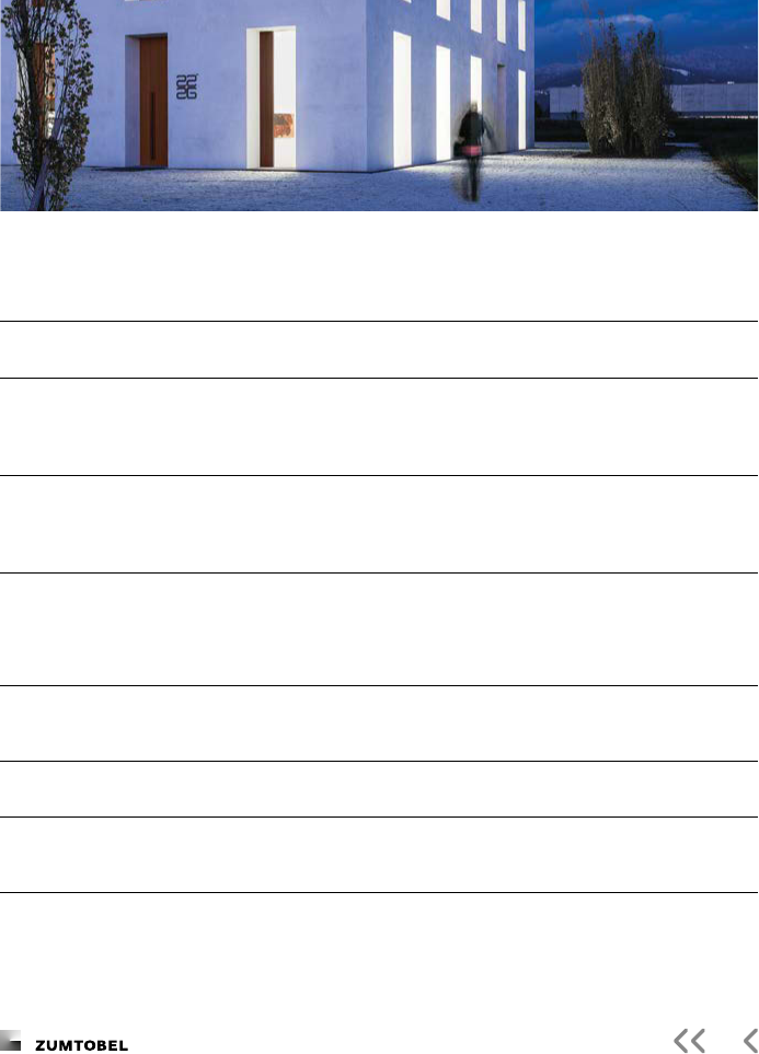
Light for Outdoor and Architecture
Application areas
Human experience
Social factors – Give back an urban environment to people at night
– Encourage interaction
– Create interesting places that are just begging to be discovered
– Support human activities
Emotional factors – Turn familiar streets into something new and unexpected
– Adapt the light to habits and needs
Perception-related factors – Highlight urban details and give people the chance to experience
their surroundings in a new way
– Improve the general perception, feeling of well-being and comfort
of a location
– Orientation
Sustainability and sensibility
Ecological factors – Lower the energy consumption with the help of high-quality light
sources and optical systems
– Avoid light pollution: this means more than just pointing the light
towards the ground. Rather, sensible design strategies are aimed at
enhancing rooms and improving the three-dimensional perception.
Design factors – To always illuminate places correctly and at the right time with
adaptive systems, without wasting light
– Create a balance between articial light and darkness (starting from
the natural situation at night): This reduces the energy consumption
in the system and improves the visual quality

The Lighting Handbook
Intelligent systems are becoming increasingly
important in outdoor areas too and represent
an important step towards achieving sustain-
able goals. In the context of a human and
sociocentric approach, it can be understood
as part of a complete design process. Semi-
autonomous systems are hereby controlled
on the basis of human behaviour (presence
detection), their activities and emotions
(changing colour temperature) and the times
of the day.
The Zumtobel outdoor portfolio covers
intelligent DMX or DALI devices that allow
greater exibility to control every single
luminaire.
According to our application approach, we
oer adaptive lighting solutions that allow
light segmentation for individual luminaires
using multi-channel devices. This method
opens the door to lighting design where the
luminaires can full various design tasks from
a single position.
Adaptability and identity
Social identity factors – Improve the quality of life and unique experiences through local
identity
– Feel good during interactions: this encourages a sense of belonging
to the place and community, thus creating a social identity
Design factors – Help to change an empty space into living space
– Create a non-static identity: light is based on how people use a
certain room at certain times.
– Create a lighting environment to make spaces more inviting
Multilayer design approach with Active Light
Layers of light – Individually dene the way a room is experienced at night
– Present the three-dimensional room precisely: subtle dynamics
improve the human experience of certain places at certain times.
– Various layers change in relation to the current activity
(or time span)
Toolbox of light – Choose from modular concepts: adapt light to the design require-
ments, but still ensure consistent design across projects and spaces
– Combine precision with visual comfort through adjustable optics
– “Composite Beam” concept
– Simple and exible installation, easy adjustment on site
– Choose a uniform and integrated design language for the
entire room
– Future-safe control and integration in further systems
Customer benets of lighting management and Active Light

The Lighting Handbook
Scenes can be comfortably recalled at the
press of a button with the control units. The
mood in a room can be changed completely
by dened static or dynamic lighting scenes.
For example, a kitchen-cum-living room with
a high luminous intensity and light with few
shadows can be optimised for the needs of
work in the kitchen. It later becomes the
central communication point to welcome
guests with a glass of champagne in cosy
reddish, dimmed light.
The living area can also have a supportive
biological eect on health. Dynamic light
scenes are dened to create a natural and
healthy transition to relaxing sleep in the
evening with a reduced, reddish light. In the
morning, the special sense cells on the retina
are activated to the highest intensity through
a higher share of bluish light.
We improve the quality and eect of light in private domestic and living space
– Thanks to our unique network of architects and planners, our
application knowledge and the latest LED and control technology
We cut installation and operating costs
– Through our profound understanding of users’ needs, smart,
sustainable lighting solutions and professional support in all phases
of a project
We encourage well-being and health
– Through bioactive lighting systems and settings, developed on the
basis of continuous research.
Application areas
Light for Living
Customer benets of lighting management and Active Light

The Lighting Handbook
Chapter
Technology
Key parameters in the lighting catalogue
Data sheet
LED technology
Functions and types of LEDs
LED features
Important LED key gures
Technology used in Zumtobel’s LED modules
Light control technology
Optics
Technology and application in products

The Lighting Handbook
Key parameters in the lighting catalogue
All of the terminology used and basic technical calcula-
tion methods correspond to the recommendations of the
gui
deline “Planning reliability in LED lighting” of the ZVEI
(
nd
edition; last revised: March ).
The data sheet provided for each luminaire
in the electronic catalogue contains key data
for correct planning with Zumtobel luminaires.
) Luminaire name and article number
) Text for call for tenders
) Photo and dimensions
) Light distribution
(LID: Luminous Intensity Distribution)
– The luminous intensities are shown in the
unit cd/klm ( klm lm). The oper-
ating eciency of the luminaries h is
taken into account in the LID. In order to
determine the absolute luminous intensi-
ties, reference is made to the luminaire’s
light output for LED luminaires and to the
lamp’s light output for luminaires with
conventional light sources.
– The operating eciency of hLED lumi-
naires is set to since the eciency
is already taken into account in the
luminaire’s light output.
) Key parameters:
Light source Type and name
Luminaire’s light output*: [lm]
Luminaire’s luminous ecacy*: [lm/W]
Min. colour rendering index: R
a
or CRI
Control gear: [designation]
Correlated colour temperature*: [K] in Kelvin
Colour coordinates tolerance (initial MacAdam)*: Levels of ellipses
Mean rated lamp life*: e.g. h L at °C
Luminaire output*: [W] input power, tw. with lambda .
Standby power*: [W]
Control: Details of trigger device
Maintenance category: Type of maintenance, see chapter
All values marked * are rated values
The parameters are described in more detail in the section on “LED Technology” (see page ).
The permissible operating temperatures are shown in some cases, whereby the light output, power consumption,
colour temperature and lamp life can vary by up to within the named range.

The Lighting Handbook
Colour code
The colour code is a three-digit numerical
value (e.g. ) that describes the lighting
quality of a white light source. The rst digit
denotes colour rendering, the second and
third digits denote colour temperature (light
colour).
Example:
xx colour rendering index
x colour temperature K
Risk groups
In principle, all light sources have to be
tested with respect to their possible harmful
eect for human eyes (EN - [],
EN Photobiological safety of lamps and
lamp systems). Their safety is conrmed by
the CEsymbol. Damage to the retina by
optical radiation hereby depends on:
– the spectral shares
– the radiation strength
– how long the person looks into the
light source
Light sources are classied in
risk groups (RG):
– RG : No general risk
– RG : No risk with normal use
– RG : No risk with natural aversion
reactions
– RG : Risk with even a eeting glance
If it is dangerous to “stare” into a light source
for a longer period of time, RG has to be
marked with the following symbol:
Zumtobel luminaires do not in principle
constitute a danger for human eyes. All of
our luminaires fall under RG or , so that
they do not have to be marked.
Maintenance and dismantling
Notes on maintenance and dismantling as
required by EU Directive / can be
found as a download in the electronic
catalogue.
Guarantee and warranty
Notes on the warranty terms can be found
in the electronic catalogue under “-year
warranty”.
Symbol: Do not stare into
light source/luminaire!
Source: © VDE
More details of the luminaires can be found in the electronic catalogue

The Lighting Handbook
Functions and types of LEDs
An LED (light-emitting diode) is an electronic
semiconductor component that emits light
when a current ows through it. The wave-
length of the light depends on the semicon-
ductor material and its doping. The spectrum
of LEDs oers a major benet: only light
(electromagnetic radiation in the visible
range) and no ultraviolet or infrared radiation
is emitted.
Basically, there are three types of LED:
– Standard through-hole LED: often used as
indicator light source, although with low
light output. Due to their shorter service
life, higher probability of failure and sensi-
tivity to UV radiation, they are not used in
lighting technology.
– SMD (surface mounted device) LED: an LED
that is reow-soldered to the surface of a
printed circuit board (using a reow oven).
Basically, it consists of an LED chip pro-
tected by silicon coating mounted in or on
a housing or a ceramic plate with contacts.
– CoB (chip on board) LED: the LED chip is
mounted directly on the printed circuit
board. This allows a dense arrangement of
chips close to each other.
LED features
– High eciency high luminous ecacy
(lumen/watt)
– Long service life
– Broad spectrum of white light
(warm white to daylight white)
– No UV or infrared radiation
– Compact size
– Good to excellent colour rendering
index (R
a
)
– Luminous ux and service life highly
tempera ture-sensitive
– No environmentally harmful materials
(e.g. mercury)
– Resistant to vibrations and impact
– Saturated colours
– Immediate start, i.e. luminous ux
after switching on
– No ignition, boosting or cooling time
– High-precision digital dimming
– No shifting of colour locations during
dimming
– Luminous ux and service life greatly
dependent on temperature (increase at
lower temperatures)
LED technology

The Lighting Handbook
Light output, output and luminous ecacy
The light output, output and luminous
ecacy are important key parameters to
describe the eciency of LED luminaires. The
luminaire manufacturer has to specify these
parameters for all of their luminaires. This
information contains the losses in the light-
deecting and light-shielding components of
the luminaire and thus the eect of the
operating eciency of the luminaire. The
operating eciency is not normally shown
separately for LED -luminaires.
ATTENTION: The light output and luminous
ecacy for built-in LED modules are higher
than those of the luminaires, so that these
cannot be compared with each other.
The values are quoted as rated values.
This takes into account the fact that minor
uctuations may occur between the individual
measured values during the production
period of luminaire type as a consequence
of production conditions. Unless otherwise
specied, the values apply for an ambient
temperature of °C.
Rated light output of LED luminaires
Initial illuminance at the start of operation
(lm). The maximum deviation may be –
(tolerance).
Rated output of LED luminaires
Initial input power of a luminaire (W).
The maximum deviation may be
(tolerance).
Luminous ecacy of LED luminaires
Initial value for the ratio of light output to
input power (lm/W).
Constant light output
If constant light output technology is used,
the light output of a luminaire remains
constant over the lamp life. The measured
output rises to the maximum value relative to
the reduction in light output of the LED type
used. This maximum input power corresponds
to the initial value with a maximum light
output.
Note: CLO: constant light output.
Important LED key gures
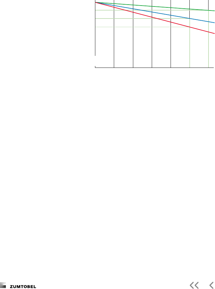
The Lighting Handbook
A service life of , h corresponds to
continuous operation for around . years.
When quoting longer service lives, it has to
be considered which operating times would
be necessary for these. With the normal
operating times in oce use of , h per
year, a service life of , h corresponds
to a presence time of years.
Apart from the mean service life, the total
failure rate AFV (Abrupt Failure Value) can
also be quoted. This refers to the total failure
of the modules in the luminaire and is nor-
mally less than .
A failure of the control gear is excluded
here. This has to be quoted separately and is
normally covered by the warranty terms for
the control gear.
Note to B and B:
By values are statistical values: they mean
that y percent of the product-based criteria
are not fullled. However, a method exists
that allows such statistics to be safely calcu-
lated in advance for a longer operating time.
B identies an approximate man value
for the reduction in luminous ux. B names
o luminaires that do not satisfy one
criterion. This lead to the false assumption
that B luminaires last longer than B lumi-
naires.
What is correct is that service lives as
long as these cannot be measured but only
calculated. Whereas B can be derived from
known forecasting methods, there is no
method for B that is described in technical
instructions. For this reason, those service life
gures not further specied on a Zumtobel
data sheet relate to B. B has only be-
come established for street lighting.
A maintenance factor can be determined for
dierent presence times for various types of
LED luminaires with a service life specication
(see chapter ).
LED technology
Service life in hours
//
h L
h L
h L
The service life describes the time
until the mean light output of an
LED luminaire has dropped to a
specied percentage of the initial
light output.
Example: Service life “L
, h” means that the light
output has dropped to of
the initial value after , h
operating time.
It is common to quote the
“mean rated service life”.
Service life data for LEDs
Relative
light output in

The Lighting Handbook
White light quality and binning
In the production of LED chips, LEDs of
die rent production batches have dierent
properties with respect to intensity, colour
temperature, colour location, or with respect
to forward voltage.
The properties of each individual LED are
measured after manufacturing and allocated
to a group showing the same features.
These correspond to nely dierentiated
para meters which are divided into so-called
bins. Depending on the application and the
product, these features are weighted
dierent ly.
By using specic binning groups, colour
and brightness tolerances – not just of the
light emitted by individual luminaires, but
also on visible luminous surfaces – are
reduced to a minimum. Thus, illuminated
surfaces and light emitting panels of lumi-
naires are given a uniform appearance. This
selection is especial ly important when it
comes to “single LED” products and applica-
tions with maximum white light quality such
as museums.
In practice, MacAdam ellipses are often
used to give users an idea of how far individ-
ual LED modules dier with respect to colour
perception.
MacAdam ellipses describe the colour
distan ces on the xy coordinates in the stand-
ardised colour table. In theory, we talk about
MacAdam as soon as there is a visual dier-
ence with respect to colour percep tion.
A colour dierence between individual
LED modules of one luminaire and between
individual LEDs, i.e. individual luminaires in
case of spotlights, of MacAdam ellipses is at
present considered the maximum of technical
feasibility. The colour dierence between
wide-angle luminaires with high luminous ux
levels (replacing uorescent lamps) is consid-
ered excellent at MacAdam ellipses.
MacAdam ellipses along the Planck curve for white light
6500 K
5700 K
5000 K
4500 K
4000 K
3500 K
3000 K
2700 K

The Lighting Handbook
Colour temperature and CCT
Colour temperature (CT)
– Colour temperature, as well as light colour,
in warm, neutral and daylight white
– Corresponds to colour tines in white,
quoted as the Correlated Colour
Temperature (CCT) in Kelvin (K)
– Colour coordinates of the Planckian radiator
(Planckian curve)
– Real light sources often deviate from this:
correlated colour temperature (CCT)
– Judd straight lines: all points on these lines
have the same correlated colour tempera-
ture. This means that dierent colour
coordinates can have the same CCT.
stableWhite
Invariable colour temperature
– Specic initial colour temperature
(incl. tolerance range)
– Most frequent colour temperature at
Zumtobel: K, K
– No readjustment in the course of the LED’s
service life
– Temperature-based readjustment to keep
the colour temperature constant
– Constant colour temperature during
dimming
Technology used in Zumtobel’s LED modules
700
0.9
0.8
0.7
0.6
0.5
0.4
0.3
0.2
0.1
0.0
y
x
0.0 0.1 0.2 0.3 0.4 0.5 0.6 0.7 0.8
∞
10000
6000
4000
3000
2500
2000
1500
T
C
(°K)
520
540
560
580
600
620
500
490
480
460
470
380
700
0.9
0.8
0.7
0.6
0.5
0.4
0.3
0.2
0.1
0.0
y
x
0.0 0.1 0.2 0.3 0.4 0.5 0.6 0.7 0.8
∞
10000
6000
4000
3000
2500
2000
1500
T
C
(°K)
520
540
560
580
600
620
500
490
480
460
470
380
LED technology

The Lighting Handbook
700
0.9
0.8
0.7
0.6
0.5
0.4
0.3
0.2
0.1
0.0
y
x
0.0 0.1 0.2 0.3 0.4 0.5 0.6 0.7 0.8
∞
10000
6000
4000
3000
2500
2000
1500
T
C
(°K)
520
540
560
580
600
620
500
490
480
460
470
380
700
0.9
0.8
0.7
0.6
0.5
0.4
0.3
0.2
0.1
0.0
y
x
0.0 0.1 0.2 0.3 0.4 0.5 0.6 0.7 0.8
∞
10000
6000
4000
3000
2500
1500
T
C
(°K)
520
540
560
580
600
620
500
490
480
460
470
380
2000
non-calibrated
Balanced tunableWhite
– Manual control of two colour
temperature ranges
– Colour temperature between K
and K
– Brightness and/or light output depends on
the control of the light colours
– Greater tolerances with MacAdams levels
– Controlled via DALI device type or
two separate channels
Calibrated tunableWhite
– Control of calibrated (pre-set) colour
temperatures
– Colour temperatures near the
Planck curve within MacAdams levels
– Colour temperature between K
and K
– Constant light output over the entire
colour temperature range
– Constant colour temperature during
dimming
– Control of the two channels via DALI
device type
Expert tunableWhite
– Control of the colour temperature
precisely along the Planck curve
(MacAdam )
– Colour rendering R
a
– Colour temperature between K
and K
– Very constant light output over the entire
colour temperature range
– Constant colour temperature during
dimming
– Control of several channels via DALI
device type
tunableWhite refers to the deliberate change of the colour temperature.
A dierentiation is hereby made between the following qualities:

The Lighting Handbook
Optics
The direction of light is based on three fundamental
principles: reection, refraction and diraction.
These principles are applied to dene the photometric
properties of luminaires in terms of lighting patterns.
High-precision light direction structures made of
tried-and-tested as well as innovative materials extend
the range with a view to both optics and design.
Reection
In physics, reection is the change in direction of a
wavefront at an interface between two media with a
diering refractive index so that the wavefront returns to
the medium from which it originated.
Specular reection
Nearly all light is reected according to
the law of reection (incident angle
reected angle). The aim is to reect as
much light as possible, absorbing only
little of it.
Lambertian reectance
Nearly all light is reected diusely:
light is reected in all directions, in
accor dance with Lambert’s law, so
that the reecting surface appears
equally bright from any direction of
view. Here, too, the aim is to reect
as much light as possible and absorb
only
little of it.
Total reection
A beam of light coming from a medium
with a higher refractive index that hits
the boundary to a medium with a
lower refractive index will be reected
awa
y from the incident slot. If the
incident angle is further increased, total
reection will occur at a critical angle.
This means that the light beam does
not pass out from the material with a
higher refractive index, but is reected
back.
Light control technology
higher
refractive
index
l
ow
er
refractive
index
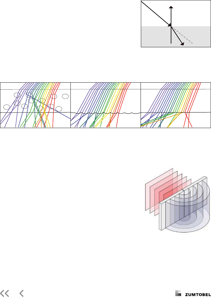
The Lighting Handbook
Refraction
Refraction indicates the change in direction of a wave
due to a spatial change in its rate of propagation. For
light waves in particular this phenomenon is described by
the refraction index of a medium.
At the transition between two media with a diering
refraction index, the beam therefore changes direction
according to Snell’s law of refraction.
Diraction
If light encounters periodic structures with expansions in
the wavelength of light, it is diracted (see illustration).
Such structures may be transmission grids, reection
grids (phase grids) or holographic grids, for example.
Diraction of chromatic light results in an unfolding of the
light spectrum.
Light refraction in materials
with dierent optical properties
Light refraction against structures
such as microprisms or microlenses
Ligh
t refraction against very ne
structures for thorough mixing of light
Medium
Medium
θ
1
θ
2
In: ZVEI Guidelines, Planning reliability in LED lighting,
available from: www.licht.de

The Lighting Handbook
Technology Illustration of the principle Functional principle Application in products Application hints/benets
Reector/lens system The LED’s narrow-beam light is emitted
through a lens and a bi-symmetrical
reector so that a narrow ly targeted
beam pattern is produced.
RESCLITE escape
The structural design of the light control unit results in a light output
ratio of the luminaire of up to . Wide-angle distribution of indirect
light allows uniform illumination of the ceiling even at short suspension
heights.
Rotating lens A cascading lens system redirects the
vertical light beams, producing unilater-
ally asymmetrical distribution of light.
ERI (Escape Route Illumination)
in ON
LITE CROSSIGN an
d
ONLITEPURESIGN
With an installed load of only . W, the spot illuminates up to m of
escape route. The lens can be adjusted in increments of °. By using
two lenses, escape route illumination can be doubled and even escape
route illumination around the corner can be implemented.
Lasered light guide
panel
The texture applied on a transparent
plastic panel using a laser results in
refraction of the light injected. Thanks
to the texture’s varying density, the
entire light guide panel can be
uniformly illuminated.
ONLITE PURESIGN
This technology allows unilateral injection of light resulting in an
increase in eciency while at the same time ensuring perfect uniformity.
Split-lens technology The light is guided by multiple total
reection in the lens. This produces a
very homogeneous appearance of the
lens with dierent beam angles.
TECTON C
The precise direction of light allows the realisation of dierent beam
characteristics with no additional reectors. The luminaire cross-section
and thus the appearance also remain identical.
Technology and application in products
Light control technology

The Lighting Handbook
Technology Illustration of the principle Functional principle Application in products Application hints/benets
Reector/lens system The LED’s narrow-beam light is emitted
through a lens and a bi-symmetrical
reector so that a narrow ly targeted
beam pattern is produced.
RESCLITE escape
The structural design of the light control unit results in a light output
ratio of the luminaire of up to . Wide-angle distribution of indirect
light allows uniform illumination of the ceiling even at short suspension
heights.
Rotating lens A cascading lens system redirects the
vertical light beams, producing unilater-
ally asymmetrical distribution of light.
ERI (Escape Route Illumination)
in ON
LITE CROSSIGN an
d
ONLITEPURESIGN
With an installed load of only . W, the spot illuminates up to m of
escape route. The lens can be adjusted in increments of °. By using
two lenses, escape route illumination can be doubled and even escape
route illumination around the corner can be implemented.
Lasered light guide
panel
The texture applied on a transparent
plastic panel using a laser results in
refraction of the light injected. Thanks
to the texture’s varying density, the
entire light guide panel can be
uniformly illuminated.
ONLITE PURESIGN
This technology allows unilateral injection of light resulting in an
increase in eciency while at the same time ensuring perfect uniformity.
Split-lens technology The light is guided by multiple total
reection in the lens. This produces a
very homogeneous appearance of the
lens with dierent beam angles.
TECTON C
The precise direction of light allows the realisation of dierent beam
characteristics with no additional reectors. The luminaire cross-section
and thus the appearance also remain identical.

The Lighting Handbook
Technology Illustration of the principle Functional principle Application in products Application hints/benets
Micro-pyramidal optic The light is coupled into the MPO
panel from above. The light beams are
precisely directed, resulting in a glare-
reduced distribution of light that is
thus suitable for use in oces. This
optic is also used in a miniaturised
form as MPO lm.
LIGHT FIELDS, AERO, MELLOW LIGHT V
The luminance of the LEDs is reduced over the entire light-emitting
surface, allowing a exible arrangement of the luminaires at the
workplace.
Micro-lens optic The lm uses the lens eect to paral-
lelize the light and thus produce a
linear light distribution.
MELLOW LIGHT V
A certain percentage of the light is radiated more horizontally from the
light-emitting surface. This increases the vertical luminous intensity
compared to louvre luminaires and thus improves the face and object
recognition as well as wall illumination.
Virtual light source
technology
The evenly backlit cluster of lenses
directs the light so that little at light
can escape from the luminaire. This
results in a pleasant brightness with a
high light output.
MELLOW LIGHT evo
lution / innity
The principle of backlighting and the transformation of the selective
light sources on virtual, full-surface light emission creates a uniform
appearance. The brightness levels are pleasant and correspond to the
typical character of “mellow light”.
Edge-Lit technology An optimised microstructure has been
embossed on a transparent -plastic
panel to create an asymmetric light
distribution. At the same time, the
luminaire’s light-emitting surface ap-
pears to be homogeneously lit.
CAE
LA wall-mounted luminaire
The asymmetric beam creates optimum lighting conditions in corridors
through sucient vertical luminous intensities with a -simultaneous
reduction of the brightnesses in the eld of view. This facilitates orienta-
tion and increases safety.
Mixing-chamber
lens system
The LEDs’ spectral components are
united in the mixing chamber to pro-
duce white light, focussed by the lens
and directed to the high-precision
reec tor.
IYON
The division into mixing chamber and optic results in high modularity
when using various reectors, and hence a variety of beam patterns –
from narrow-beam to wide-angle.
Light control technology

The Lighting Handbook
Technology Illustration of the principle Functional principle Application in products Application hints/benets
Micro-pyramidal optic The light is coupled into the MPO
panel from above. The light beams are
precisely directed, resulting in a glare-
reduced distribution of light that is
thus suitable for use in oces. This
optic is also used in a miniaturised
form as MPO lm.
LIGHT FIELDS, AERO, MELLOW LIGHT V
The luminance of the LEDs is reduced over the entire light-emitting
surface, allowing a exible arrangement of the luminaires at the
workplace.
Micro-lens optic The lm uses the lens eect to paral-
lelize the light and thus produce a
linear light distribution.
MELLOW LIGHT V
A certain percentage of the light is radiated more horizontally from the
light-emitting surface. This increases the vertical luminous intensity
compared to louvre luminaires and thus improves the face and object
recognition as well as wall illumination.
Virtual light source
technology
The evenly backlit cluster of lenses
directs the light so that little at light
can escape from the luminaire. This
results in a pleasant brightness with a
high light output.
MELLOW LIGHT evo
lution / innity
The principle of backlighting and the transformation of the selective
light sources on virtual, full-surface light emission creates a uniform
appearance. The brightness levels are pleasant and correspond to the
typical character of “mellow light”.
Edge-Lit technology An optimised microstructure has been
embossed on a transparent -plastic
panel to create an asymmetric light
distribution. At the same time, the
luminaire’s light-emitting surface ap-
pears to be homogeneously lit.
CAE
LA wall-mounted luminaire
The asymmetric beam creates optimum lighting conditions in corridors
through sucient vertical luminous intensities with a -simultaneous
reduction of the brightnesses in the eld of view. This facilitates orienta-
tion and increases safety.
Mixing-chamber
lens system
The LEDs’ spectral components are
united in the mixing chamber to pro-
duce white light, focussed by the lens
and directed to the high-precision
reec tor.
IYON
The division into mixing chamber and optic results in high modularity
when using various reectors, and hence a variety of beam patterns –
from narrow-beam to wide-angle.

The Lighting Handbook
Technology Illustration of the principle Functional principle Application in products Application hints/benets
Free-form reector
liteCarve
®
The free-form reector oers very
precise and balanced, rectangular light
distribution right up to the edge areas.
Used in front of an LED point light
source, the reector directs the light
completely indirectly and specically to
the vertical surfaces.
INTRO liteCarve
®
– also for
-phase tracks
A single liteCarve
®
luminaire creates a homogeneously lit area for
which up to three spotlights previously had to be used. This simplies
planning because rectangular light distributions can be easily placed
next to each other without overlaps.
Double lens system The light cone can be quickly and easily
adjusted for spot-on accent lighting via
the wedge-shaped lenses set into the
tube. The light cone can be rotated
around ° by rotating the tube.
PANOS innity Adjustable
The wide ranging PANOS product group allows dierent beam
characteristics to be achieved leading to a homogeneous visual ceiling
appearance. The look of the ceiling remains soothing and unobtrusive.
TIR optic with
free-form lens
The combination of TIR optic (Total
Internal Reection) and a free-form lens
array directs the relatively wide light
beam of the LED in parallel.
SUPERSYSTEM II Wal
lwasher Mini
The beam characteristic of the wallwasher creates uniform wall
illumination and is ideal for use in rooms up to metres in height.
TIR optic with snoot The wide light beam from the LED is
directed in parallel with the help of the
TIR optic (Total Internal Reection).
The desired light distributions can be
achieved by using various snoots
(e.g. lms).
SUPERSYSTEM II LED
spotlight
The special technology permits beam angles from Superspot (°) to
Wideood (°) for LED spotlights.
Light control technology

The Lighting Handbook
Technology Illustration of the principle Functional principle Application in products Application hints/benets
Free-form reector
liteCarve
®
The free-form reector oers very
precise and balanced, rectangular light
distribution right up to the edge areas.
Used in front of an LED point light
source, the reector directs the light
completely indirectly and specically to
the vertical surfaces.
INTRO liteCarve
®
– also for
-phase tracks
A single liteCarve
®
luminaire creates a homogeneously lit area for
which up to three spotlights previously had to be used. This simplies
planning because rectangular light distributions can be easily placed
next to each other without overlaps.
Double lens system The light cone can be quickly and easily
adjusted for spot-on accent lighting via
the wedge-shaped lenses set into the
tube. The light cone can be rotated
around ° by rotating the tube.
PANOS innity Adjustable
The wide ranging PANOS product group allows dierent beam
characteristics to be achieved leading to a homogeneous visual ceiling
appearance. The look of the ceiling remains soothing and unobtrusive.
TIR optic with
free-form lens
The combination of TIR optic (Total
Internal Reection) and a free-form lens
array directs the relatively wide light
beam of the LED in parallel.
SUPERSYSTEM II Wal
lwasher Mini
The beam characteristic of the wallwasher creates uniform wall
illumination and is ideal for use in rooms up to metres in height.
TIR optic with snoot The wide light beam from the LED is
directed in parallel with the help of the
TIR optic (Total Internal Reection).
The desired light distributions can be
achieved by using various snoots
(e.g. lms).
SUPERSYSTEM II LED
spotlight
The special technology permits beam angles from Superspot (°) to
Wideood (°) for LED spotlights.


The Lighting Handbook
Introduction – History of electric lighting, overview
Our ancestors had to make do with natural
sunlight for many thousands of years. The
story of how humans rst learned to use light
begins years ago when they rst
tamed re. It then became possible to use
light and heat purposefully, and articial
lighting has extended the natural day length
ever since.
Wood, tallow, fat and oil were burned to
provide light for many years. It was industri-
alisation that brought really revolutionary
changes in its wake: rst gas, then elec tricity
became the dominant method of
distributing energy and producing light.
Articial electric lighting has been an
almost ubiquitous feature of everyday life for
more than years now. Our modern life-
style is not viable without articial lighting.
We live in a -hour society and spend most
of our time indoors. Even our outdoor envi-
ronment is illuminated, either for trac
management purposes or to obtain decora-
tive eects.
Demand for articial lighting is therefore
huge, and we have high expectations of it:
we expect articial lighting to be available
any time, anywhere and in the required
quality – and we expect it to be produced
aordably and in eco-friendly ways.
Modern light sources are now highly e-
cient and produce good-quality light. Lighting
in Europe nevertheless still accounts for
of all energy consumption (and around
of worldwide energy consumption).
Professional lighting accounts for approxi-
mately of this gure, and lighting in
private homes accounts for roughly .
That is equivalent to the emission of climate-
relevant greenhouse gases amounting to
roughly million tonnes of CO
a year.
Saving energy that is used for lighting
therefore also saves CO
. The EU has set
ambitious targets intended to limit global
warming to no more than °C compared with
pre-industrial levels: – by and
– by compared with emission
levels.
The lighting industry has come up with a
wide variety of dierent types of lamps since
when Thomas Alva Edison invented
the incandescent lamp and manufactured it
on an industrial scale. Individual lamps dier
in terms of their design and output and,
especially, the way in which they produce
light. The most important criteria for modern
light sources are lighting quality and e-
ciency – low energy consumption and a long
service life.
Light production
Light can be produced in a large number of
dierent ways – naturally or articially.
Light is produced cost-eectively by using
four main groups of light sources:
– Thermal light sources
– Low-intensity discharge lamps
– High-intensity discharge lamps
– Semiconductor light sources

The Lighting Handbook
Light production
Thermal radiation
Thermal light sources
Gas discharge
Discharge lamps
Electroluminescence
Semiconductor light sources
Incandes-
cent lamps
Light emitting diodesHigh-intensity
discharge
lamps
Low-intensity
discharge
lamps
Halogen
incandescent
lamps
Standard,
reector,
special types
V V
Standard,
reector, cap at
b
ot
h ends
Fluorescent
lamps, compact
uorescent
lamps, “energy-
saving lamps”
Metal halide
lamps, sodium
discharge lamps,
mercury dis-
charge lamps
L
ED la
mps,
LED modules,
OLED

The Lighting Handbook
Halogen incandescent lamps
– Mains voltage or low voltage
– Service life and luminous eciency better
than incandescent lamps
– Dimmable
– Brilliant light
– Excellent colour rendering
– Use: retail and domestic areas,
hospitality and decorative applications
Functional description
Current ows through a lament and heats
it up in exactly the same way as in an incan-
descent lamp. This is why these lamps relea se
relatively large amounts of heat. The halogen
cycle boosts the eciency and prolongs the
service life of these lamps compared with
conventional incandescent lamps.
Low-voltage lamps are very compact and
therefore ideally suitable for directing light
precisely, but they do need a transformer.
Due to European legislation, only the most
energy-ecient versions of this lamp group
are permitted.
More ecient alternatives include compact
uorescent lamps with built-in electronic
ballasts or LED lamps.
QR
QA QT-DE QPAR QPAR
QR-CBC
The most important light sources
QT

The Lighting Handbook
Fluorescent lamps
– High to very high luminous eciency
(especially T HE)
– Good to very good colour rendering
– Long service life
– Wide selection of standard ranges
– Dimmable
– Use: ecient wide-area lighting
Functional description
An alternating electrical eld between two
electrodes in the discharge tube produces
invisible UV radiation. The tube’s white
uorescent coating converts this radiation
into high-quality, visible light.
These lamps need ignitors and current
limiting; these functions are combined in
an electronic ballast.
The luminous ux of uorescent lamps is
highly dependent on their operating position
and ambient temperature. Lamps that use
amalgam technology are optimised for use in
environments where there are uctuating
temperatures (see page ).
T T-R(I)T-IT T-D

The Lighting Handbook
Compact uorescent lamps
– Compact designs
– High luminous eciency
– Excellent colour rendering
– Wide selection of standard ranges
– Dimmable
– Use: commercial and prestigious areas,
hospitality
Functional description
These lamps are compact versions of tubular
or toroidal uorescent lamps and opera te in
a very similar way.
The luminous ux of these lamps is highly
dependent on their operating position and
ambient temperature. Lamps that use
amalgam technology are optimised for use in
environments where there are uctuating
temperatures.
TC-SEL TC-DEL TC-TEL(I)
TC-L(I)
The most important light sources

The Lighting Handbook
Metal halide lamps
– High luminous eciency
– Good to very good colour rendering
– Good colour stability in case of lamps
with ceramic discharge tubes
– Usually not dimmable
– Use: industrial bays, spotlighting,
oodlighting systems, retail areas
Functional description
Metal halide lamps maintain an extremely
compact electric arc in a discharge tube.
Lighting quality is determined by the compo-
sition of the materials the lamp contains.
An ignitor is needed to start the lamp and
the current must be limited by a ballast.
Electronic ballasts can advantageously be
used for low-power lamps.
Lamps with a ceramic discharge tube
oer the best lighting quality, eciency and
service life.
HIT-TC-CE HIT-CE HIT-DE-CE HIPAR HIE HIT

The Lighting Handbook
High-pressure sodium discharge lamps
– High luminous eciency and long
service life
– Satisfactory to poor colour rendering
– Yellowish light colour
– Can be dimmed in steps
– Use: industrial bays, street lighting,
outdoor illumination
Colour-improved (Philips SDW):
– Warm, white light
– Excellent colour rendering
– Use: retail areas
Functional description
Discharge in the elongated ceramic discharge
tube is determined by sodium. The light
therefore has a yellow hue and is only
suitable for specic applications.
Philips colour-improved SDW produces very
good quality white light and is a popular
choice for lighting in retail spaces.
An ignitor is generally needed to start
the lamp. The current must be limited by a
ballast.
HST-DEHST-CRI
HST
The most important light sources
HSE

The Lighting Handbook
Light emitting diodes (LEDs)
– Very ecient light production
– Wide selection of standard ranges
– Can be switched and dimmed as required
– Very long service life
– Good to very good colour rendering
– Very good production of coloured light
– Use: LEDs can be used for both functional
and decorative lighting in indoor and
outdoor locations.
Functional description
Light emitting diodes are modern semicon-
ductor devices. Their characteristics are
determin ed by their materials, mechanical
design and operating mode. The active semi-
conductor layer, in which radiation is pro-
LED lamp LED module
Board
LED chip
BubbleBonding wire
More information about LEDs can be
found in Chapter – Technology.
duced, is sandwiched between a positive and
a negative substrate inside the LED. Actual
coloured light is produced, depending on
which materials are chosen. Nowadays, high-
quality white light is produced by blue LEDs
with yellow luminescent substances. A mix-
ture of RGB (red, green, blue) also produces
white. The smallest LED chips have a side
length of approx. µm ( micrometre
one thousandth of a millimetre). As a rule,
they are powered via appropriate DC convert-
ers. Their very long service life of over
hours demands optimised thermal
management in order to prevent overheating.
Today, LEDs are already some of the most
ecient light sources for general lighting.
They are completely superseding traditional
light sources in many applications.

The Lighting Handbook
Properties of conventional lamps
Conventional lamps today are normally only
used as replacements. Nevertheless, there
are reasons as to why ecient conventional
lamps should still be used. Some properties
that have to be taken into account when
working with these lamps are listed below.
On account of their high luminous e-
ciency and long service life, LED light sources
in particular are dominating all applications.
They can rightly be viewed as the light source
of the future.
It is therefore up to the expertise of the
planner to nd the best possible light source
for any lighting task.
The key parameters of lamps can essen-
tially be dened by the following terms:
Warm-up time
Discharge lamps in particular need between
seconds and several minutes to warm up
and output the full luminous ux.
Re-start
High-pressure discharge lamps need to
cool down for several minutes before they
can be started again.
Dimmability
As well as incandescent and halogen
incandescent lamps, almost all uorescent
and compact uorescent lamps can be
dimmed as required nowadays. Most
manufacturers’ metal halide lamps continue
to be incompatible with dimming because
dimming may have uncontrolled eects on
lighting quality and lamp service life. The
new series of special models for indoor and
outdoor applications constitute an excep-
tion. The output of sodium vapour lamps
and high-pressure mercury lamps can be
restricted in stages. LED light sources can
be switched and dimmed as required.
Operating position
Manufacturers specify the permitted oper-
ating positions for their lamps. For some
metal halide lamps, only certain operating
positions are allowed so as to avoid unsta-
ble operating states. Compact uorescent
lamps may usually be used in any operating
position; however, important properties
such as the lumi nous ux vs. temperature
curve may vary with the position.
105°
45°
30°
h 105 s 45 p 30
admissible
not admissible

The Lighting Handbook
-
°C
T-I (amalgam lamp)
Relative luminous ux
Min. relative luminous ux in
Application hints
Luminous ux – temperature curve
As for all uorescent lamps, the lamp’s
luminous ux is temperature-dependent. The
maximum value is obtained at an optimum
ambient temperature, with losses increasing
at higher and lower temperatures. The T
basically follows the same curve as the
T, but the maximum occurs not at an
ambient temperature of to °C but at
about °C.
Reason: the cool spot of T is not located
in the centre of the lamp, but typically at
one end of the tube where the manufacturer
has xed its seal.
The rated luminous ux is generally speci-
ed for an ambient temperature of °C.
For the T, the maximum value therefore
lies above this rated value. Thus luminaire
eciencies may have levels greater than “”.
Amalgam technology
Special T-I lamps with amalgam technology
are available in order to ensure that the
luminous ux is slightly less temperature
dependent.
Adding amalgam (a mercury compound)
makes it possible to compensate for the
decrease in luminous ux at relatively high
and low temperatures.
T W
T
T W
- °C
Ambient temperature
(dashed line)
Luminous ux
Ambient temperature
Luminous ux
T uorescent lamps
In comparison with thicker T lamps (dia-
meter: mm), modern T lamps (diameter:
mm) show several dierent properties that
must be taken into account for application.

The Lighting Handbook
Lamp designations
LBS ZVEI ILCOS OSRAM PHILIPS GE SYLVANIA
A IAA TR CLASSIC TONE A Normal
QR-CBC HRGI DECOSTAR S MASTERline Precise MR Professional
QPAR HEGPAR HALOPAR PAR PAR Hi-Spot
TC FS DULUX S PL-S BIAX S Lynx CF-S
TC-T FSM DULUX T PL-T BIAX T Lynx CF-T
TC-L FSD DULUX L PL-L BIAX L Lynx CF-L
T FDH-G- FH, FQ TL’ HE, HO T XL FHE, FHO
T FD-G- L TL’D T F
HME QE HQL HPL H HSL
HIT MT HQI-T, HCI-T MHN/W-T,
CDM-T
Arcstream T,
Kolarc T, CMH
HSI-T, CMI-T
HST ST, STM, XX NAV-T SON-T, SDW-T Lucalox T SHP-T
¹ LBS Lampen-Bezeichnungs-System [Lamp Code System], a standardised system for designating electric
lamps for general lighting (luminaire manufacturers)
² ILCOS International Lamp COding System (lamp manufacturers), Standard IEC TS /DIN
Various systems are used to designate lamps.
Lamp manufacturers use their own product
name for each lamp. And there are standards
and non-proprietary documents that use gen-
eral designations. The LBS ¹ coding system,
which was devised by the Central Association
of German Electrical and Electronic Industries
(ZVEI), provides an extremely useful over-
view. Every general lighting lamp can be pre-
cisely designated according to the LBS coding
system by an abbreviation consisting of
letters and numbers.
Many luminaire manufacturers use the LBS
coding system to specify appropriate lamps
for their luminaires regardless of the names
used by lamp manufacturers. This makes
sense because many lamps are standardised
and are therefore interchangeable regar dless
of make. International standards use another
system – ILCOS ².
The table below compares the designations
used in various systems.

The Lighting Handbook
Example of general description of a uores cent lamp using the LBS coding system:
T W /
. Colour temperature K (warm white)
.. Colour rendering index to
W Nominal wattage W
L.. Low-pressure discharge lamp
.M. Mercury vapour
(LM)T Tubular
mm tube diameter
The LBS lamp coding system makes it
possible to designate a uorescent lamp
precisely.
Redundant or unambiguous details may
sometimes be omitted, for instance “LM” for
“low-pressure mercury vapour discharge
lamp” as in this example.
Besides this basic data, further details can be
specied depending on the lamp:
bulb colour, clear or frosted,
radiation angle in case of reector lamps,
description of cap/lampholder,
permissible voltage etc.

The Lighting Handbook
Chapter
Lighting control and control gear
Communication protocols
Terminology and circuit diagram
DALI: General information | Features
Device type
DSI: General information | Features
Dierences between DALI and DSI
DALI and DSI: Control line
LUXMATE bus:
General information | Features |
Bus domain and bus power supply
Bus line and cable lengths
Comparison: LUXMATE bus – KNX (EIB)
DMX: General information | Features | System design
Lighting control systems
LUXMATE: Simple dimming
switchDIM: General information | Wiring scheme
CIRCLE KIT: General information | Wiring scheme
LUXMATE: Overview of lighting control systems
LUXMATE DIMLITE:
General information | Overview
Selection according to control gear and functionality
Basic wiring: Dimming via
momentary-action switch using
Basic wiring: Daylight-based dimming using
Basic wiring: Multifunctional lighting control
LITECOM: General information
LITECOM innity: General information
Overview circuit for a LITECOM system
Overview circuit for a LITECOM innity system
LUXMATE LITENET:
General information | Overview circuit
LUXMATE lighting management:
Overview | Functions | Product ranges
Dierentiation between DALI (EMOTION, LITENET)
and DMX (E:cue)
Control devices
Functions overview

The Lighting Handbook
Terminology and circuit diagram
– A bus is a system for transferring data
between several participants via a joint
transmission path.
– In electronic engineering, a control line is
a connection (cable, wire) between one
transmitter and one receiver. Via this
connection the receiver is switched to a
dierent operating mode. Communication
is either bidirectional (DALI) or just uni-
directional (DSI).
– A communication protocol is an agreement
according to which data transfer bet ween
two or more participants is carried out.
In its most simple form, a proto col can be
dened as the rules deter mining the
structure, meaning and synchronisation of
communication.
Communication protocols
Momentary-
action switch
Bus
: LUXMATE, KNX
Input
module
PC or
controller
Output
module
(transmitter)
Electronic
ballast
(receiver)
Luminaire
Control line:
DALI
DSI

The Lighting Handbook
DALI: General information
– The term DALI stands for “Digital
Addressable Lighting Interface”.
– DALI is not a building management bus
system, but a protocol for digital address-
ing of technical lighting control gear.
– DALI is a standard dened by several
manufacturers of luminaires and electronic
ballasts: IEC allows the combination
of devices of various manufacturers.
However, the standard denes only output
devices (control gear), not input devices
such as sensors or control units. Hence,
input devices with DALI connection are
addressed in a manufacturer-specic way!
– IEC species requirements placed
on control gear allocated to specic types
of device.
DALI: Features
– Usable data transmission rate: bit/s
– Max. control units per control circuit
– Max. groups per control gear can
be assigned
– Max. scenes per control unit can be
programmed
– Bidirectional: reports information such as
faulty lamps, dimming levels etc.
– Max. system current of mA from
central interface supply (each electronic
ballast takes up a maximum of mA of
current load)
– Two-wire control line (potential-free,
polarity-free, unshielded, no terminal
resis tors)
– Voltage drop between transmitter and
recei ver must not be more than V
– Application: general lighting (small number
of lighting points, static light)

The Lighting Handbook
DALI: Device type
IEC subcommittee SC C is in charge of the IEC
“Digital addressable lighting interface” series of standards.
IEC -xx Parts xx: General requirements
IEC -:- Part : System
IEC -:- Part : Control devices
IEC -xx
Parts xx: Particular requirements for control gear
IEC -:- Part : Fluorescent lamps (device type )
IEC -:- Part : Emergency lighting with separate battery (device type )
IEC -:- Part : Discharge lamps (except uorescent lamps) (device type )
IEC -:- Part : LV halogen lamps (device type )
IEC -:- Part : Supply voltage controllers for incandescent lamps
(device type )
IEC -:- Part : Conversion from digital signal into D. C. voltage
(device type )
IEC -:- Part : Particular requirements for control gear –
LED modules (device type )
IEC -:- Part : Switching function (device type )
IEC -:- Part : Colour/colour temperature control (device type )
IEC -:- Part : Sequencer (device type )
Communication protocols

The Lighting Handbook
DSI: General information
– The term DSI stands for “Digital Serial
Interface”.
– DSI is not a building management bus sys-
tem, but a protocol for digital addressing of
technical lighting control gear.
– DSI is a manufacturer-specic interface
dened by Zumtobel.
– DSI is the predecessor of DALI with the
main goal of replacing analogue addressing
(– V) of control gear with digital
addressing.
– Devices with DSI and DALI connection are
not compatible and cannot be used jointly
in one control circuit.
Dierences between DALI and DSI
– Each DALI control unit may have dierent
intensity levels, while all DSI (and – V)
control units always have the same inten-
sity level.
– With DSI, units are allocated to groups
by wiring; with DALI, group allocation is
performed via software.
– With DSI (and – V), only a unidirec tional
ow of information (from the controller to
the controlled unit) is possible.
– DSI and DALI units cannot be operated
jointly in one control circuit.
DSI: Features
– Usable data transmission rate: bit/s
– Depending on the output module:
to control units per control circuit
– Max. scenes per control unit can be
programmed
– Unidirectional: reports only faulty lamps
(depending on the technical design of the
electronic ballast)
– Two-wire control line (potential-free,
polarity-free, unshielded, no terminal
resis tors)
– Application: general lighting (small number
of lighting points, static light)

The Lighting Handbook
DALI and DSI: Control line
– Any type of insulated line for mains
voltage is admissible if the voltage drop is
not more than V at mA.
– DALI components are usually powered
via a separate mains power supply.
– The insulation of the digital interface
complies with basic insulation require-
ments; verication is eected in accord-
ance with the IEC standard.
Thus, SELV (Safety Extra Low Voltage)
is not guaranteed.
– The cables connecting the digital interface
with the mains power supply lines (e.g.
V) may be relocated if the in sulation
conditions ( x basic insulation) are
maintained. The two “free” wires of a
x .mm² NYM cable are frequently used
as control lines (together with the other
wires for phase, neutral and protective
ground conductors).
Cross-section Length
x . mm² m
x . mm² m
x . mm² m
x . mm² m
Neutral conductor
DALI (DA)
DALI (DA)Phase
Protective
earth
e.g. NYM x ...
Communication protocols

The Lighting Handbook
LUXMATE bus: General information
– Proprietary bus developed by Zumtobel,
so that a combination of devices by
dierent manufacturers is not possible
– Bus domain, the smallest logical unit
– Max. rooms
– Max. addresses per room
– Max. groups per room
– Max. devices connected to
bus coupler (max. devices per
bus power supply)
LUXMATE bus:
Bus domain and bus power supply
– Bus domain
– Smallest logical unit
– Max. rooms
– Max. addresses per room
– Max. devices connected with
bus coupler
– Bus power supply
– LM-BV: maximum of modules
– LM-BVS: maximum of modules
LM-BV (LM-BVS) bus power supply
LM-BK bus coupler
LUXMATE bus: Features
– Usable data transmission rate: bit/s
– Max. scenes per control unit can be
programmed
– Bidirectional: reports information
– Two-wire control line (potential-free,
polarity-free, unshielded, no terminal
resis tors)
– Loop resistance for entire line within one
bus domain must not exceed ohms
– Total length of line: max. m
(with x . mm²)
– Dimming range to
– Application: general lighting (large number
of lighting points, static light)
Room 3
Adress 1 2 3 ... 99
Room 2
Adress 1 2 3 ... 99
Room 1
Adress 1 2 3 ... 99
Room 3
Adress 1 2 3 ... 99
Room 2
Adress 1 2 3 ... 99
Room 1
Adress 1 2 3 ... 99
Room 3
Adress 1 2 3 ... 99
Room 2
Adress 1 2 3 ... 99
Room 1
Adress 1 2 3 ... 99

The Lighting Handbook
LUXMATE bus: Bus line and cable lengths
Bus line
– Twisted two-core line ( lay each
metres) for low-voltage installation
Cable lengths
– Overall length for one bus power supply:
max. m
– Between LUXMATE devices (AB):
– Max. m with x . mm²
– Max. m with x . mm²
– From bus power supply to the most
distant LUXMATE device (A,B):
– Max. m with x . mm²
– Max. m with x . mm²
– Loop resistance in a bus circuit must not
exceed ohms (applies to all components
of the bus power supply).
– Bus and mains in one cable ( x . mm²)
are admissible only for m stub lengths
each.
– For tracks/trunking: bus lines should be
cross-linked at least every m.
Voltage measurement (VOLT): measurement
bet
ween B and B – D. C. voltage
Current measurement (AMPERE): measurement at B
or B – measured value must not exceed mA
Loop resistance (OHM): ) disconnect LM-BV from
power, ) establish wire bridge at LM-BV between
B and B, ) perform measurement at the last actuator
of th
e bus line between B and B.
The loop resistance measured must not exceed ohms!
If a loop resistance between and ohms
is measured, the service report must indicate
that the bus line is too long; electrician must be inform
ed!
If the loop resistance measured is ohms or higher,
commissioning will be terminated!
The cable length is calculated as follows:
Cable length loop resistance x rho x cross-section/
div
ided by two
L R x rho x A / :
A cross-section/rho for copper
LUX
MATE guidelines:
. mm cross-section max. bus line of m
. mm cross-section max. bus line of m/
with x x . cable, both pairs must be connected
. mm cross-section max. bus line of m
. mm cross-section max. bus line of m
Communication protocols
Cross-section Length
x . mm² m
x . mm² m
x . mm² m
x . mm² m
Cable length test report LUXMATE PROFESSIONAL
A ≤ 350 m AB ≤ 350 m
B ≤ 350 mLM-BV
B
A

The Lighting Handbook
Temperature
Binary output
Actuators
Sensors
Blinds actuator
Blinds
Dimming/switching
actuator
Lighting
Switching
actuator
Ventilator
Supply voltage
Mometary-
action
switch
Threshold value indicator
Blinds sensor
Binary input
230 VAC BUS line 1
Timer
Comparison: LUXMATE bus – KNX (EIB)
LUXMATE
– Standard cables are used for installation
– Protected against reversed polarity!
– General operation immediately after installation (installation test)
– Easy addressing from each location within the building
KNX
– A specially shielded EIB cable must be used for installation
– Not protected against reversed polarity (/–)
– No operation possible without addressing (no installation test)
– Addressing only directly on the luminaire and via control points using special ETSsoftware
Actuators
Sensors
TCP/IP
LITENET flexis N2
with server functionality
PC with LITENET insite
management software
LITENET netlink
LITENET netlink
DALI
3 x 64 Address
LUXMATE bus
Control
points
Sensors LuminairesSensors Control
points
Windows Screens Blinds

The Lighting Handbook
DMX: General information
DMX was developed in the United States for
stage equipment in . Previously, the
slider settings for spotlights were converted
to analogue voltage levels between and
V. Subsequently these voltages were trans-
mitted in parallel to the dimmers via one
control line for each spotlight.
This analogue dimming worked well with a
small number of spotlights. However, stages
and shows became bigger and bigger. The
cabling included a large number of parallel
– V control lines became too complex and
inexible.
Only the positions of the slider have been
converted to digital values for the DMX.
ALL dimming levels are then transmitted one
after the other via ONE joint control line.
DMX: Features
– Usable data transmission rate:
bit/s
– Refresh rate: times per second
– Max. channels (addresses) per universe
(control circuit)
– Max. of luminaires directly one after
the other; for more luminaires, a splitter
is required
– Unidirectional: no information is reported
– Two-wire control line
(shielded, terminal resistance)
– Application: illumination of façades (large
number of lighting points, dynamic light)
Communication protocols

The Lighting Handbook
DMX: System design
DMX signal generator
DMX splitter
Data IN Data IN
Data OUT Data OUT
Data IN Data IN
DMX luminaire
Addr. –
DMX luminaire
Addr. –
DMX luminaire
Addr. –
DMX luminaire
Addr. –
DMX luminaire
Addr. –
DMX luminaire
Addr. –
Terminal
resistor
Terminal
resistor
Data OUT Data OUT
Data IN Data IN
Data OUT Data OUT
max. receivers in case of standard DMX connection
Data OUT


The Lighting Handbook
switchDIM: General information
Benets
– Easiest way of dimming an individual
lumi naire or a small group of luminaires
– Only a conventional momentary-action
switch is required
– No addressing necessary
Features
– Function:
– Switching by pressing the button briey
– Dimming by pressing the button longer
– Asynchronous dimming: switching time
(approx. . seconds) depends on the timer
in the control unit. Due to component
tolerances, there is no exact switching
point for several luminaires within a group.
Asynchronicity may occur.
– Recommendation: use switchDIM for no
more than luminaires. If more luminaires
are involved, a controller such as DIMLITE
single is feasible.
– Works only with a momentary-action
switch, not with a regular switch!
Wiring of electronic ballast with switchDIM function.
DALI N
L
D1
C2DSI
switchDIM

The Lighting Handbook
N
L
PE
DA
N
L
DA
DA
DA
CIRCLE tune
3 scene keys
Benets
– CIRCLE KIT: easiest way of applying
lighting scenes
– CIRCLEtune KIT: easiest way of using
colour temperature control
– Commissioning and operation via
CIRCLE CSx control point
– Several CIRCLE control points can be
connected in parallel
– Bus power supply already included in
the package
Features
– lighting scenes can be individually
programm ed
– Dimming of luminaire groups
– Bus power supply for up to
DALI-dimmable luminaires
– One CIRCLE control point covers
DALI loads
– Control point available in white and silver
CIRCLE KIT: Wiring scheme
CIRCLEtune KIT: Wiring scheme
Lighting control systems
Control devices
Control devices
L phase
N neutral
PE protective earth
D control line
v earth
~
–
AC voltage
EMOTION BV2
bus power supply
Mains 230 V/50 Hz
N
L
PE
DA
N
L
DA
DA
DA
CIRCLE tune
CIRCLE KIT and CIRCLE tune KIT: General information
12
11
9
10
N
L
PE
DA
N
L
DA
N
L
DA
DA
DA
DA
L
N
DA
DA
DALI-CSx
Complete package for 2 lighting groups and 3 lighting scenes
Lamp control gearLamps
DALI control line
e.g. NYM x . mm²
up to m long DALI electronic ballasts
DALI-BV
bus power supply
scene keys lighting groups
DALI LED luminaires
e.g. PANOS infinity
DALI LED luminaires
e.g. LIGHT FIELDS evolution
Fluorescent lamps T/T
TC-L/TC-DEL/TC-TELMains V/ Hz
Control unitsControl devices
Scene call-up
Lighting scene : “screen-based work” Lighting scene : “good morning”Lighting scene : “conference”
Individual control of
luminaire groups
Group :
indirect light
Group :
direct light
Control and programming via
CIRCLE CSx control point
Several CIRCLE control points can
be connected in parallel
Control point available in white
or silver
DALI Standard
Up to luminaires can be
connected via DALI
Easy to install and commission
Bus supply included in
package
PCA, PHD, TE, max. off

The Lighting Handbook
Lamp control gear/Lamps
Lamp control gear/Lamps
Control units
Control units
N
L
PE
DA
N
L
DA
DA
DA
CIRCLE tune
DALI control line
e.g. NYM 2 x 1.5 mm²
up to 300 m long
3 scene keys 2 lighting groups
PCA, PHD, TE, max. 64 off
tunableWhite luminaires
e.g. ARCOS
CIRCLE KIT: Wiring scheme
CIRCLEtune KIT: Wiring scheme
EMOTION BV2
bus power supply
12
11
9
10
N
L
PE
DA
N
L
DA
N
L
DA
DA
DA
DA
L
N
DA
DA
DALI-CSx
Complete package for 2 lighting groups and 3 lighting scenes
Lamp control gearLamps
DALI control line
e.g. NYM x . mm²
up to m long DALI electronic ballasts
DALI-BV
bus power supply
scene keys lighting groups
DALI LED luminaires
e.g. PANOS infinity
DALI LED luminaires
e.g. LIGHT FIELDS evolution
Fluorescent lamps T/T
TC-L/TC-DEL/TC-TELMains V/ Hz
Control unitsControl devices
Scene call-up
Lighting scene : “screen-based work” Lighting scene : “good morning”Lighting scene : “conference”
Individual control of
luminaire groups
Group :
indirect light
Group :
direct light
Control and programming via
CIRCLE CSx control point
Several CIRCLE control points can
be connected in parallel
Control point available in white
or silver
DALI Standard
Up to luminaires can be
connected via DALI
Easy to install and commission
Bus supply included in
package
PCA, PHD, TE, max. off

The Lighting Handbook
LUXMATE: Overview of lighting control systems
LUXMATE DIMLITE
Lighting management for individual rooms
LUXMATE LITENET / PROFESSIONAL
Lighting management for buildings
with lighting and blinds control
DMX lighting management
Dynamic lighting scenarios for
outer façades
Lighting control systems
LITECOM innity
Lighting management for buildings and
building complexes
LITECOM
Lighting management for smaller buildings

The Lighting Handbook
Benets
– Synchronous dimming
– AUTO detect: DALI and DSI outputs with
automatic identication (mixed operation
not admissible)
– AUTO setup: automatic initialisation,
no addressing necessary
– Reduction of stand-by losses: automatic
power disconnection of lighting actuators
via integrated relay
– Operation using all conventional V
momentary-action light switches;
several momentary-action switches can
be connect ed in parallel
Features
– models: for installation in switch cabinet
for or luminaire groups, and for
installation in luminaire or recessed into
ceiling for or luminaire groups,
including strain relief
– Up to lighting scenes, of which scene
features daylight-based control (depending
on additional devices)
– Modular range of functions, to be indi-
vidually combined:
– daylight-based control
– presence detector
(ONLY OFF, ON/OFF, CORRIDOR with
dimming level)
– IR remote control
– CIRCLE comfort control point
( groups, scenes)
– scene or group module
LUXMATE DIMLITE: General information

The Lighting Handbook
LUXMATE DIMLITE: Overview
Size of system
DIMLITE basic module
Number of groups
Number of DALI luminaires
Number of DSI luminaires
Dimming
Lighting scene
Control by momentary-
action switch
P
re
sence detector
Daylight-based control
Convenience control point
Remote control
DIMLITE single*
DIMLITE daylight*
DIMLITE multifunction ch**
DIMLITE multifunction ch**
* for installation in luminaire or recessed into ceiling
** for installation in switch cabinet (DIN rail mounted device)
Func
tions
Components
to be integrated
Lighting control systems

The Lighting Handbook
LUXMATE DIMLITE: Selection according to control gear and functionality
LUXMATE control unit Lamp control gear (electronic ballast, transformer, ...)
Lamps Dimming range All control gear with DALI/DSI control input
GLS lamps – Phase dimmer: –– VA
PAR lamps – Phase dimmer: –– VA
HV halogen incandescent lamps – Phase dimmer: –– VA
LV halogen incandescent lamps – electronic dimmable transformer: VA VA
Fluorescent lamps – electronic dimmable ballast
LED – electronic dimmable LED converter ch./ ch.
Module name for
Function
Control DSI/DALI/dim²save
-channel dimming, lighting scene, momentary-action switch, presence detector DIMLITE single
presence
-channel dimming, daylight, presence momentary-action switch, presence detector, DIMLITE daylight
light sensor
- or -channel multifunction momentary-action switch, Circle, light sensor, DIMLITE ch* (-channel)
presence detector, IR remote control unit
. Select appropriate lamp control gear
. Select control function required
All modules available for installation in luminaire or recess into ceiling
* only available as housing for installation in switch cabinet

The Lighting Handbook
N
L
PE
DA
DA
DA
DA
N
L
T
T
Sc
PIR
DA
DA
DA
DA
L
N
L
N
L
N
*
**
DIMLITE single
Dimming via control by momentary-action switches
Absolutely flicker-free,
synchronous dimming
Easy programming and call-up
of lighting scenes
Presence detector can be
integrated, 3 functional profiles:
ONLY OFF, ON/OFF, CORRIDOR
Dimming range max. 1–100 %
Can be operated by any
standard momentary-action light
switch 230 V
Several momentary-action
switches can be connected in
parallel
DALI auto identification
(no mixed mode)
Easy installation
Designs available: installed in
luminaire, recessed into ceiling
(using strain relief supplied)
Control units Control devices Lamp control gearLamps
* Saving the pre-set lighting level
** Alternative:
When using a single momentary-
action switch, t jumper on
terminal “T↑” und “T↓”
Snap-on strain relief
DALI LED luminaires
e.g. PANOS evolution
DALI LED luminaires
e.g. MIREL evolution
Mains V/ Hz AC
Conventional
double momentary-
action light switch
On/Off/Dim
Conventional
momentary-action
light switch
scene
Conventional
presence detector
Fluorescent lamps T/T
TC-L/TC-DEL/TC-TEL
DALI control line
e.g. NYM x . mm²,
up to m long
DALI electronic ballasts
max. control gear
LUXMATE DIMLITE basic wiring:
Dimming via momentary-action switch using
Lighting control systems
L phase
N neutral
PE protective earth
T momentary-action
switch input
D control line
v earth
~
–
AC voltage

The Lighting Handbook
N
L
PE
DA
DA
DA
DA
N
L
T
T
Sc
PIR
DA
DA
DA
DA
L
N
L
N
L
N
*
**
DIMLITE single
Dimming via control by momentary-action switches
Absolutely flicker-free,
synchronous dimming
Easy programming and call-up
of lighting scenes
Presence detector can be
integrated, 3 functional profiles:
ONLY OFF, ON/OFF, CORRIDOR
Dimming range max. 1–100 %
Can be operated by any
standard momentary-action light
switch 230 V
Several momentary-action
switches can be connected in
parallel
DALI auto identification
(no mixed mode)
Easy installation
Designs available: installed in
luminaire, recessed into ceiling
(using strain relief supplied)
Control units Control devices Lamp control gearLamps
* Saving the pre-set lighting level
** Alternative:
When using a single momentary-
action switch, t jumper on
terminal “T↑” und “T↓”
Snap-on strain relief
DALI LED luminaires
e.g. PANOS evolution
DALI LED luminaires
e.g. MIREL evolution
Mains V/ Hz AC
Conventional
double momentary-
action light switch
On/Off/Dim
Conventional
momentary-action
light switch
scene
Conventional
presence detector
Fluorescent lamps T/T
TC-L/TC-DEL/TC-TEL
DALI control line
e.g. NYM x . mm²,
up to m long
DALI electronic ballasts
max. control gear
N
L
PE
DA
DA
DA
DA
N
L
T
T
Sc
PIR
DA
DA
DA
DA
L
N
L
N
L
N
*
**
DIMLITE single
Dimming via control by momentary-action switches
Absolutely flicker-free,
synchronous dimming
Easy programming and call-up
of lighting scenes
Presence detector can be
integrated, 3 functional profiles:
ONLY OFF, ON/OFF, CORRIDOR
Dimming range max. 1–100 %
Can be operated by any
standard momentary-action light
switch 230 V
Several momentary-action
switches can be connected in
parallel
DALI auto identification
(no mixed mode)
Easy installation
Designs available: installed in
luminaire, recessed into ceiling
(using strain relief supplied)
Control units Control devices Lamp control gearLamps
* Saving the pre-set lighting level
** Alternative:
When using a single momentary-
action switch, t jumper on
terminal “T↑” und “T↓”
Snap-on strain relief
DALI LED luminaires
e.g. PANOS evolution
DALI LED luminaires
e.g. MIREL evolution
Mains V/ Hz AC
Conventional
double momentary-
action light switch
On/Off/Dim
Conventional
momentary-action
light switch
scene
Conventional
presence detector
Fluorescent lamps T/T
TC-L/TC-DEL/TC-TEL
DALI control line
e.g. NYM x . mm²,
up to m long
DALI electronic ballasts
max. control gear
Snap-on
strain relief

The Lighting Handbook
L
N
DA
DA
L
N
DA
DA
N
L
T1
PIR/Sc
DA
DA
DA
DA
S1
S2
G1
G2
N
L
PE
DIMLITE daylight
T2
G I G II
DIMLITE daylight
Group 1
Group 2
LSD
daylight sensor
Group 1
Group 2
Momentary-
action switch
DALI channel 2
DALI channel 1
Mains
DALI channel 2
Mains
Presence
detector
SensorsControl units Control devices Lamp control gearLamps
Absolutely flicker-free,
synchronous dimming
Automatic daylight-based
control
Alternatively: integration of one
lighting scene or a presence
detector possible
Dimming range max. 1 –100 %
Presence detector with 3
functional profiles: ONLY OFF,
ON/OFF, CORRIDOR
Can be operated by any
standard momentary-action
light switch 230 V
Several momentary-action swit-
ches can be connected in parallel
DALI auto identification
(no mixed mode)
Easy installation
Designs available: installed in
luminaire, recessed into ceiling
(using strain relief supplied) or
already built into luminaire
Control line: DALI
Mains
LSD daylight sensor
Momentary-action
switch control
Master luminaire:
DIMLITE daylight
Slave luminaire: DALI
Daylight-based dimming
snap-on strain relief
Fluorescent lamps T/T
TC-L/TC-DL/TC-TEL
Conventional
double momen-
tary-action light
switch
On/Off/Dim
Interior illuminance
sensor LSD
Light sensor line
e.g. NYM x . mm², max. m long
DALI control circuit
e.g. NYM x . mm²,
max. m long
DALI/DSI electronic ballast
Group I (max. control units)Mains V/ Hz AC
Conventional
presence
detector
Alternatively:
conventional
momentary-
action light
switch scene
DALI LED luminaires
e.g. MIREL evolution
LUXMATE DIMLITE basic wiring:
Daylight-based dimming using
Lighting control systems
L phase
N neutral
PE protective earth
T momentary-action
switch input
D control line
v earth
~
–
AC voltage

The Lighting Handbook
L
N
DA
DA
L
N
DA
DA
N
L
T1
PIR/Sc
DA
DA
DA
DA
S1
S2
G1
G2
N
L
PE
DIMLITE daylight
T2
G I G II
DIMLITE daylight
Group 1
Group 2
LSD
daylight sensor
Group 1
Group 2
Momentary-
action switch
DALI channel 2
DALI channel 1
Mains
DALI channel 2
Mains
Presence
detector
SensorsControl units Control devices Lamp control gearLamps
Absolutely flicker-free,
synchronous dimming
Automatic daylight-based
control
Alternatively: integration of one
lighting scene or a presence
detector possible
Dimming range max. 1 –100 %
Presence detector with 3
functional profiles: ONLY OFF,
ON/OFF, CORRIDOR
Can be operated by any
standard momentary-action
light switch 230 V
Several momentary-action swit-
ches can be connected in parallel
DALI auto identification
(no mixed mode)
Easy installation
Designs available: installed in
luminaire, recessed into ceiling
(using strain relief supplied) or
already built into luminaire
Control line: DALI
Mains
LSD daylight sensor
Momentary-action
switch control
Master luminaire:
DIMLITE daylight
Slave luminaire: DALI
Daylight-based dimming
snap-on strain relief
Fluorescent lamps T/T
TC-L/TC-DL/TC-TEL
Conventional
double momen-
tary-action light
switch
On/Off/Dim
Interior illuminance
sensor LSD
Light sensor line
e.g. NYM x . mm², max. m long
DALI control circuit
e.g. NYM x . mm²,
max. m long
DALI/DSI electronic ballast
Group I (max. control units)Mains V/ Hz AC
Conventional
presence
detector
Alternatively:
conventional
momentary-
action light
switch scene
DALI LED luminaires
e.g. MIREL evolution
L
N
DA
DA
L
N
DA
DA
N
L
T1
PIR/Sc
DA
DA
DA
DA
S1
S2
G1
G2
N
L
PE
DIMLITE daylight
T2
G I G II
DIMLITE daylight
Group 1
Group 2
LSD
daylight sensor
Group 1
Group 2
Momentary-
action switch
DALI channel 2
DALI channel 1
Mains
DALI channel 2
Mains
Presence
detector
SensorsControl units Control devices Lamp control gearLamps
Absolutely flicker-free,
synchronous dimming
Automatic daylight-based
control
Alternatively: integration of one
lighting scene or a presence
detector possible
Dimming range max. 1 –100 %
Presence detector with 3
functional profiles: ONLY OFF,
ON/OFF, CORRIDOR
Can be operated by any
standard momentary-action
light switch 230 V
Several momentary-action swit-
ches can be connected in parallel
DALI auto identification
(no mixed mode)
Easy installation
Designs available: installed in
luminaire, recessed into ceiling
(using strain relief supplied) or
already built into luminaire
Control line: DALI
Mains
LSD daylight sensor
Momentary-action
switch control
Master luminaire:
DIMLITE daylight
Slave luminaire: DALI
Daylight-based dimming
snap-on strain relief
Fluorescent lamps T/T
TC-L/TC-DL/TC-TEL
Conventional
double momen-
tary-action light
switch
On/Off/Dim
Interior illuminance
sensor LSD
Light sensor line
e.g. NYM x . mm², max. m long
DALI control circuit
e.g. NYM x . mm²,
max. m long
DALI/DSI electronic ballast
Group I (max. control units)Mains V/ Hz AC
Conventional
presence
detector
Alternatively:
conventional
momentary-
action light
switch scene
DALI LED luminaires
e.g. MIREL evolution
Snap-on
strain relief

The Lighting Handbook
LUXMATE DIMLITE basic wiring:
Multifunctional lighting control
Lighting control systems
L phase
N neutral
PE protective earth
D control line
max. 300 m
at 1.5 mm²
max. 8 ED units
max. 300 m
at 1.5 mm²
max. 25 DALI
per channel
Channels 3 + 4
only with
DIMLITE multi-
function 4ch
ED-EYE light
sensor
ED-SENS
(PD+IR)
Multi-sensor
IRTOUCHED-IR
infrared
receiver
ED-SxED
group module
ED-SxED
lighting scene
module
CIRCLE Cxx
control point
comfort control unit
Load
contactor
(optional)
Relay
Control IN
Presence
detector
T26/T16 TC-L/
TC-DEL/TC-TEL
fluorescent lamps
T26/T16 TC-L/
TC-DEL/TC-TEL
fluorescent lamps
T26/T16 TC-L/
TC-DEL/TC-TEL
fluorescent lamps
Group
1
Lighting scene /
automatic daylight-
based control
(only 4ch)
All
groups
Group
2
Group
3
Group
4
DALI HFG (1 DALI load)
DALI HFG (1 DALI load)
DALI HFG (1 DALI load)
optional mains
isolation facility
Multifunctional lighting control
Compact lighting control unit for
2/4 luminaire groups
DALI outputs with automatic
identi cation
Reducing stand-by loss:
automatic power disconnection
of lighting actuators via integra-
ted relay
Modular range of functions,
to be individually combined:
- daylight-based control
- presence detectors /
movement sensors ONLY OFF,
ON/OFF, CORRIDOR
- infrared remote control unit
- CIRCLE comfort control unit
- lighting scene module
- group module
Up to 3 lighting scenes, one
of them with daylight-based
control (depending on additional
devices)
AUTO setup: automatic initialisa-
tion, no addressing required
DIMLITE multifunction 2ch two-
channel unit and DIMLITE mul-
tifunc
tion 4ch four-channel unit
are identical except for the num-
ber of output channels and corre-
sponding key inputs
AUTO setup function: each time
the power returns to the unit, the
system will be initialised automa-
tically
Maximum cable length for all
control lines (Control-IN, DALI):
max. 300 m each at 1.5 mm²
The DIMLITE outputs are DALI
broadcast - no addressing is
required during commissioning.
Groups are assigned by wiring
the lighting actuators accordingly
Maximum of 25 DALI units (25
DALI loads) per output channel
Only Zumtobel ED units may be
connected to Control-IN. Maxi-
mum of 8 ED units at Control IN
(exception ED-EYE: max. 1 light
sensor)
ED-SENS presence detector can
be assigned to individual groups
via IR remote control
Installation of light sensor: sur-
face-mounted on the ceiling,
directed towards the window
Lighting scenes and daylight
settings are entered using key
combinations
If a light sensor is installed,
Lighting Scene 1 will always call
up the daylight programme; all
available groups will always be
subject to daylight-based control
Up to 3 lighting scenes, depen-
ding on the control unit used;
each control unit will always call
up the same scene 1, 2, 3 or OFF
The functions of the “ED-SxED”
ED unit may be selected using the
integrated rotary switch: either
scene module (1, 2, 3, OFF) or
group module (dimming of Group
1, 2, 3, 4).
CIRCLE control unit calls up three
lighting scenes and OFF; the two
rocker control switches will dim
Lighting Groups 1 and 2; Lighting
Groups 3 and 4 cannot be indivi-
dually dimmed
Conventional 230 V momentary-
action switches can be connected
to the momentary-action switch
inputs
PIR input to connect a conventio-
nal movement sensor
Relay for mains cut-o : 16 A
resistive load; in case of higher
loads or capacitive/inductive
loads, an external power contac-
tor is recommended
Design notes
DALI LED luminaire
e.g. MIREL evolution
DALI LED luminaire
e.g. PANOS evolution
max. 300 m
at 1.5 mm²
max. 8 ED units
max. 300 m
at 1.5 mm²
max. 25 DALI
per channel
Channels 3 + 4
only with
DIMLITE multi-
function 4ch
ED-EYE light
sensor
ED-SENS
(PD+IR)
Multi-sensor
IRTOUCHED-IR
infrared
receiver
ED-SxED
group module
ED-SxED
lighting scene
module
CIRCLE Cxx
control point
comfort control unit
Load
contactor
(optional)
Relay
Control IN
Presence
detector
T26/T16 TC-L/
TC-DEL/TC-TEL
fluorescent lamps
T26/T16 TC-L/
TC-DEL/TC-TEL
fluorescent lamps
T26/T16 TC-L/
TC-DEL/TC-TEL
fluorescent lamps
Group
1
Lighting scene /
automatic daylight-
based control
(only 4ch)
All
groups
Group
2
Group
3
Group
4
DALI HFG (1 DALI load)
DALI HFG (1 DALI load)
DALI HFG (1 DALI load)
optional mains
isolation facility
Multifunctional lighting control
Compact lighting control unit for
2/4 luminaire groups
DALI outputs with automatic
identi cation
Reducing stand-by loss:
automatic power disconnection
of lighting actuators via integra-
ted relay
Modular range of functions,
to be individually combined:
- daylight-based control
- presence detectors /
movement sensors ONLY OFF,
ON/OFF, CORRIDOR
- infrared remote control unit
- CIRCLE comfort control unit
- lighting scene module
- group module
Up to 3 lighting scenes, one
of them with daylight-based
control (depending on additional
devices)
AUTO setup: automatic initialisa-
tion, no addressing required
DIMLITE multifunction 2ch two-
channel unit and DIMLITE mul-
tifunction 4ch four-channel unit
are identical except for the num-
ber of output channels and corre-
sponding key inputs
AUTO setup function: each time
the power returns to the unit, the
system will be initialised automa-
tically
Maximum cable length for all
control lines (Control-IN, DALI):
max. 300 m each at 1.5 mm²
The DIMLITE outputs are DALI
broadcast - no addressing is
required during commissioning.
Groups are assigned by wiring
the lighting actuators accordingly
Maximum of 25 DALI units (25
DALI loads) per output channel
Only Zumtobel ED units may be
connected to Control-IN. Maxi-
mum of 8 ED units at Control IN
(exception ED-EYE: max. 1 light
sensor)
ED-SENS presence detector can
be assigned to individual groups
via IR remote control
Installation of light sensor: sur-
face-mounted on the ceiling,
directed towards the window
Lighting scenes and daylight
settings are entered using key
combinations
If a light sensor is installed,
Lighting Scene 1 will always call
up the daylight programme; all
available groups will always be
subject to daylight-based control
Up to 3 lighting scenes, depen-
ding on the control unit used;
each control unit will always call
up the same scene 1, 2, 3 or OFF
The functions of the “ED-SxED”
ED unit may be selected using the
integrated rotary switch: either
scene module (1, 2, 3, OFF) or
group module (dimming of Group
1, 2, 3, 4).
CIRCLE control unit calls up three
lighting scenes and OFF; the two
rocker control switches will dim
Lighting Groups 1 and 2; Lighting
Groups 3 and 4 cannot be indivi-
dually dimmed
Conventional 230 V momentary-
action switches can be connected
to the momentary-action switch
inputs
PIR input to connect a conventio-
nal movement sensor
Relay for mains cut-o : 16 A
resistive load; in case of higher
loads or capacitive/inductive
loads, an external power contac-
tor is recommended
Design notes
DALI LED luminaire
e.g. MIREL evolution
DALI LED luminaire
e.g. PANOS evolution

The Lighting Handbook
max. 300 m
at 1.5 mm²
max. 8 ED units
max. 300 m
at 1.5 mm²
max. 25 DALI
per channel
Channels 3 + 4
only with
DIMLITE multi-
function 4ch
ED-EYE light
sensor
ED-SENS
(PD+IR)
Multi-sensor
IRTOUCHED-IR
infrared
receiver
ED-SxED
group module
ED-SxED
lighting scene
module
CIRCLE Cxx
control point
comfort control unit
Load
contactor
(optional)
Relay
Control IN
Presence
detector
T26/T16 TC-L/
TC-DEL/TC-TEL
fluorescent lamps
T26/T16 TC-L/
TC-DEL/TC-TEL
fluorescent lamps
T26/T16 TC-L/
TC-DEL/TC-TEL
fluorescent lamps
Group
1
Lighting scene /
automatic daylight-
based control
(only 4ch)
All
groups
Group
2
Group
3
Group
4
DALI HFG (1 DALI load)
DALI HFG (1 DALI load)
DALI HFG (1 DALI load)
optional mains
isolation facility
Multifunctional lighting control
Compact lighting control unit for
2/4 luminaire groups
DALI outputs with automatic
identi cation
Reducing stand-by loss:
automatic power disconnection
of lighting actuators via integra-
ted relay
Modular range of functions,
to be individually combined:
- daylight-based control
- presence detectors /
movement sensors ONLY OFF,
ON/OFF, CORRIDOR
- infrared remote control unit
- CIRCLE comfort control unit
- lighting scene module
- group module
Up to 3 lighting scenes, one
of them with daylight-based
control (depending on additional
devices)
AUTO setup: automatic initialisa-
tion, no addressing required
DIMLITE multifunction 2ch two-
channel unit and DIMLITE mul-
tifunc
tion 4ch four-channel unit
are identical except for the num-
ber of output channels and corre-
sponding key inputs
AUTO setup function: each time
the power returns to the unit, the
system will be initialised automa-
tically
Maximum cable length for all
control lines (Control-IN, DALI):
max. 300 m each at 1.5 mm²
The DIMLITE outputs are DALI
broadcast - no addressing is
required during commissioning.
Groups are assigned by wiring
the lighting actuators accordingly
Maximum of 25 DALI units (25
DALI loads) per output channel
Only Zumtobel ED units may be
connected to Control-IN. Maxi-
mum of 8 ED units at Control IN
(exception ED-EYE: max. 1 light
sensor)
ED-SENS presence detector can
be assigned to individual groups
via IR remote control
Installation of light sensor: sur-
face-mounted on the ceiling,
directed towards the window
Lighting scenes and daylight
settings are entered using key
combinations
If a light sensor is installed,
Lighting Scene 1 will always call
up the daylight programme; all
available groups will always be
subject to daylight-based control
Up to 3 lighting scenes, depen-
ding on the control unit used;
each control unit will always call
up the same scene 1, 2, 3 or OFF
The functions of the “ED-SxED”
ED unit may be selected using the
integrated rotary switch: either
scene module (1, 2, 3, OFF) or
group module (dimming of Group
1, 2, 3, 4).
CIRCLE control unit calls up three
lighting scenes and OFF; the two
rocker control switches will dim
Lighting Groups 1 and 2; Lighting
Groups 3 and 4 cannot be indivi-
dually dimmed
Conventional 230 V momentary-
action switches can be connected
to the momentary-action switch
inputs
PIR input to connect a conventio-
nal movement sensor
Relay for mains cut-o : 16 A
resistive load; in case of higher
loads or capacitive/inductive
loads, an external power contac-
tor is recommended
Design notes
DALI LED luminaire
e.g. MIREL evolution
DALI LED luminaire
e.g. PANOS evolution
max. 300 m
at 1.5 mm²
max. 8 ED units
max. 300 m
at 1.5 mm²
max. 25 DALI
per channel
Channels 3 + 4
only with
DIMLITE multi-
function 4ch
ED-EYE light
sensor
ED-SENS
(PD+IR)
Multi-sensor
IRTOUCHED-IR
infrared
receiver
ED-SxED
group module
ED-SxED
lighting scene
module
CIRCLE Cxx
control point
comfort control unit
Load
contactor
(optional)
Relay
Control IN
Presence
detector
T26/T16 TC-L/
TC-DEL/TC-TEL
fluorescent lamps
T26/T16 TC-L/
TC-DEL/TC-TEL
fluorescent lamps
T26/T16 TC-L/
TC-DEL/TC-TEL
fluorescent lamps
Group
1
Lighting scene /
automatic daylight-
based control
(only 4ch)
All
groups
Group
2
Group
3
Group
4
DALI HFG (1 DALI load)
DALI HFG (1 DALI load)
DALI HFG (1 DALI load)
optional mains
isolation facility
Multifunctional lighting control
Compact lighting control unit for
2/4 luminaire groups
DALI outputs with automatic
identi cation
Reducing stand-by loss:
automatic power disconnection
of lighting actuators via integra-
ted relay
Modular range of functions,
to be individually combined:
- daylight-based control
- presence detectors /
movement sensors ONLY OFF,
ON/OFF, CORRIDOR
- infrared remote control unit
- CIRCLE comfort control unit
- lighting scene module
- group module
Up to 3 lighting scenes, one
of them with daylight-based
control (depending on additional
devices)
AUTO setup: automatic initialisa-
tion, no addressing required
DIMLITE multifunction 2ch two-
channel unit and DIMLITE mul-
tifunc
tion 4ch four-channel unit
are identical except for the num-
ber of output channels and corre-
sponding key inputs
AUTO setup function: each time
the power returns to the unit, the
system will be initialised automa-
tically
Maximum cable length for all
control lines (Control-IN, DALI):
max. 300 m each at 1.5 mm²
The DIMLITE outputs are DALI
broadcast - no addressing is
required during commissioning.
Groups are assigned by wiring
the lighting actuators accordingly
Maximum of 25 DALI units (25
DALI loads) per output channel
Only Zumtobel ED units may be
connected to Control-IN. Maxi-
mum of 8 ED units at Control IN
(exception ED-EYE: max. 1 light
sensor)
ED-SENS presence detector can
be assigned to individual groups
via IR remote control
Installation of light sensor: sur-
face-mounted on the ceiling,
directed towards the window
Lighting scenes and daylight
settings are entered using key
combinations
If a light sensor is installed,
Lighting Scene 1 will always call
up the daylight programme; all
available groups will always be
subject to daylight-based control
Up to 3 lighting scenes, depen-
ding on the control unit used;
each control unit will always call
up the same scene 1, 2, 3 or OFF
The functions of the “ED-SxED”
ED unit may be selected using the
integrated rotary switch: either
scene module (1, 2, 3, OFF) or
group module (dimming of Group
1, 2, 3, 4).
CIRCLE control unit calls up three
lighting scenes and OFF; the two
rocker control switches will dim
Lighting Groups 1 and 2; Lighting
Groups 3 and 4 cannot be indivi-
dually dimmed
Conventional 230 V momentary-
action switches can be connected
to the momentary-action switch
inputs
PIR input to connect a conventio-
nal movement sensor
Relay for mains cut-o : 16 A
resistive load; in case of higher
loads or capacitive/inductive
loads, an external power contac-
tor is recommended
Design notes
DALI LED luminaire
e.g. MIREL evolution
DALI LED luminaire
e.g. PANOS evolution

The Lighting Handbook
LITECOM: General information
Lighting control systems
Application
A single LITECOM controller is enough for
small buildings or a single oor. If the system
is expanded to a LITECOM innity system,
several existing controllers are linked with
one another. The opposite way is also possi-
ble at any time. By removing them from the
system, each controller can again be trans-
ferred to the self-sucient LITECOM mode
with addresses.
Technical data
Permissible cable lengths
Cable cross-section Max. cable length DALI Max. cable length LM
Jointly with mains in Jointly with mains in
the same cable the same cable
. mm² m m m m
. mm
² m m m m
. mm
² m m m m
. mm
² m m m m
System limit
addresses per LITECOM system
x DAL
I incl. DALI voltage supply with
bus loads (
mA) per DALI line
DALI units per DALI line
DALI ED units per DALI line
x L
M sy
stem bus (without bus power supply)
Test switch and status LED for each DALI chain
x Ethernet Mbits/s; RJ / CAT
Connection
Plug-in screw terminals for one-wire or ne-wire cables
with cross-section ranging from . to . mm
Typ
e of installation
DIN rail mounting (
mm DIN rail acc. to EN )
Space for only units required

The Lighting Handbook
LITECOM innity: General information
Technical data
Application
The number of possible addresses adds up by
linking several LITECOM controllers. A rst
generation LITECOM innity system can
comprise up to , addresses with up to
controllers and ultimately up to
,addresses will be possible.
The system can thus be exibly adjusted if
the requirements in the building change.
Permissible cable lengths
Cable cross-section
Max. cable length DALI Max. cable length LM
Jointly with mains in Jointly with mains in
the same cable the same cable
. mm² m m m m
. mm
² m m m m
. mm
² m m m m
. mm
² m m m m
System limit
addresses per LITECOM CCD
, addresses with controllers in the rst LITECOM innity generation,
, addresses in the nal expansion stage.
x DALI incl. DALI voltage supply with
bus loads (
mA) per DALI line
DALI units per DALI line
DALI ED units per DALI line
x L
M sy
stem bus (without bus power supply)
Test switch and status LED for each DALI chain
x Ethernet Mbits/s; RJ / CAT
Connection
Plug-in screw terminals for one-wire or ne-wire cables
with cross-section ranging from . to . mm
Typ
e of installation
DIN rail mounting (
mm DIN rail acc. to EN )
Space for only units required

The Lighting Handbook
TCP/IP oce network
LM Bus
DALI
DALI
DALI
LITECOM CCD Controller
LM bus without power supply, DALI lines with power supply
LM-BV Bus power supply
Blinds
LM-JAS
Motor actuator
Screens
Windows
Spotlight dimmable SEQUENCE luminaire Luminaire
dimmable
tunableWhite luminaire RGB luminaire ED-CIRCLE
Control point
LM-CIRIA
Control pointSwitchable luminaire
LM-RUKS
relay output
LM-CIRIA
Control point
Up to DALI short addresses and DALI bus loads
Notebook or PC for control, commissioning and
adjustment via Web browser
Management level
Operation and conguration via the Web
Overview circuit for a LITECOM system
Lighting control systems

The Lighting Handbook
Mobile terminal
Balanced luminaire Emergency
sign luminaire
Emergency luminaire
Switchable luminaire
EMOTION RUKS
relay output
LM-CIRCLE
Control point
LM-RCxx
Control point
LM-SxED
switch input
ED-SxED
switch input
LM-UAD
switch input
KNX
momentary-action switch/
standard switch
Conventional low-volt
momentary-action switches/
other switches
Conventional low-volt
momentary-action
switches/other switches
ED-EYE light sensor ED-SENS presence detector
Up to DALI short addresses and DALI bus loads
Up to DALI short addresses and DALI bus loads
Tablet for control, commissioning and
adjustment via Web browser
Wireless connection via router
Luminaire
dimmable
Up to DALI short addresses and DALI bus loads

The Lighting Handbook
LM Bus
DALI
DALI
DALI
LM-BV Bus power supply
Blinds
LM-JAS
Motor actuator
Screens
Windows
Spotlight dimmable SEQUENCE luminaire Luminaire
dimmable
tunableWhite luminaire RGB luminaire ED-CIRCLE
control point
LM-CIRIA
control pointSwitchable luminaire
LM-RUKS
relay output
LM-CIRIA
control point
LM-CIRCLE
control point
Up to DALI short addresses and DALI bus loads
TCP/IP oce network
LITECOM CCD Controller
LM bus without power supply
DALI lines with power supply
Laptop or PC for operation, commissioning and
adjustments using the LITECOM innity software tools
Management level
Required for conguration or control via touch panel only
Lighting control systems
Overview circuit for a LITECOM innity system

The Lighting Handbook
Balanced luminaire
LM-RCxx
control point
LM-SxED
switch input
LM-UAD
switch input
KNX
momentary-action
switch/standard switch
Conventional low-volt
momentary-action
switches/other switches
Conventional low-volt
momentary-action
switches/other switches
Up to DALI short addresses and DALI bus loads
Up to DALI short addresses and DALI bus loads
ED-SxED
switch input
ED-EYE
light sensor
ATIVO
contrast sensor
ED-SENS
presence detector
ED-M sensor
recessed into ceiling
ED-M sensor
recessed into luminaire
Switchable luminaire
EMOTION RUKS
relay output
Mobile end device for operating, commissioning and
adjusting via a web browser
Wireless connection
via router
LM-TLM
daylight
measuring head
ED-CIRCLE
control point

The Lighting Handbook
Benets
– Maximum exibility: use of oor space
(room and group addresses can be
congured via software), exibility of use
(room proles with basic functions for
specic room utilisation), modular solution
packages ranging from to
lumi naires
– Daylight-based blinds management with
central daylight sensor
– Integration of the latest technologies:
tunableWhite for LED colour temperature
luminaires, enocean for wireless key
switches, control via web browser
(LITENET incontrol)
– Maximum of energy-saving options:
daylight, presence, automated timing,
Maintenance Control (constant light
control)
– Software interfaces to building
management system: OPC, BACnet
Features
– Field technology is based on
LUXMATEProfessional with LUXMATE bus
and option al integration of DALI and
DSI control circuits
– Data exchange from PC (LITNET Flexis,
LITENET, server) to gateway (LITENET
netlink) via network technology
(TCPIP protocol)
– Gateway (LITENET netlink) allows easy
inte gration of modules in the eld area
(DALI control circuits, LUXMATE bus
link; incl. power supply) ( DALI load
mA) per DALI control circuit
Lighting control systems
TCP/IP
TCP/IP
TCP/IP
LITENET flexis N1
PC with LITENET insite
management software
LITENET netlinkLITENET netlink
DALI
3 x 64 Address
LUXMATE Bus
Control points Sensor LuminairesSensor Control points WindowsScreens Blinds
PC with LITENET insite
management software
LITENET netlinkLITENET netlink
DALI
3 x 64 Address
LUXMATE Bus
Control points Sensor LuminairesSensor Control points WindowsScreens Blinds
PC with LITENET insite
management software
LITENET netlinkLITENET netlinkLITENET flexis N1
DALI
3 x 64 Address
LUXMATE Bus
Control points Sensor LuminairesSensor Control points WindowsScreens Blinds
TCP/IP
TCP/IP
TCP/IP
LITENET flexis N1
PC with LITENET insite
management software
LITENET netlinkLITENET netlink
DALI
3 x 64 Address
LUXMATE Bus
Control points Sensor LuminairesSensor Control points WindowsScreens Blinds
PC with LITENET insite
management software
LITENET netlinkLITENET netlink
DALI
3 x 64 Address
LUXMATE Bus
Control points Sensor LuminairesSensor Control points WindowsScreens Blinds
PC with LITENET insite
management software
LITENET netlinkLITENET netlinkLITENET flexis N1
DALI
3 x 64 Address
LUXMATE Bus
Control points Sensor LuminairesSensor Control points WindowsScreens Blinds
LITENET economy
– up to output addresses
– no server required
– LITENET exisN without rotating parts (wear-free)
– optional LITENET incontrol operating software
LITENET compact
– up to output addresses
– no server required
– LITENET exis N in “ rack
– fail-safe thanks to RAID
– optional LITENET incontrol operating software
– optional BACnet and OPC interfaces
LITENET exis N2
with server func
tionality
LITENET flexis N3
with server functionality
LITENET server
LITENET economy
Package with up to 500 output addresses
• up to 500 output addresses
• no server required
• minimum installation and commissioning e ort
• LITENET exis N2 without rotating parts (wear-free)
• optional LITENET incontrol operating software
LITENET compact
Package with up to 2000 output addresses
• up to 2000 output addresses
• no server required
• minimum installation and commissioning e ort
• LITENET exis N3 in 19“ rack
• fail-safe thanks to RAID 1 (disk mirroring)
• optional LITENET incontrol operating software
• BACnet und OPC open interfaces
LITENET exibel
Package with up to 10 000 output addresses
• Between 5000 – 10 000 output addresses
(or more upon request)
• exible, radially arranged network layout
for any system topology
• can be cascaded as required
• LITENET exis N1 installed in switch cabinet
• LITENET server is extremely fail-safe thanks to
RAID 1 (disk mirroring)
• optional LITENET incontrol operating software
• BACnet und OPC open interfaces
economy - compact - exible: LUXMATE LITENET is available for buildings of every size
LITENET exis N2
with server functionality
LITENET flexis N3
with server functionality
LITENET server
LITENET economy
Package with up to 500 output addresses
• up to 500 output addresses
• no server required
• minimum installation and commissioning e ort
• LITENET exis N2 without rotating parts (wear-free)
• optional LITENET incontrol operating software
LITENET compact
Package with up to 2000 output addresses
• up to 2000 output addresses
• no server required
• minimum installation and commissioning e ort
• LITENET exis N3 in 19“ rack
• fail-safe thanks to RAID 1 (disk mirroring)
• optional LITENET incontrol operating software
• BACnet und OPC open interfaces
LITENET exibel
Package with up to 10 000 output addresses
• Between 5000 – 10 000 output addresses
(or more upon request)
• exible, radially arranged network layout
for any system topology
• can be cascaded as required
• LITENET exis N1 installed in switch cabinet
• LITENET server is extremely fail-safe thanks to
RAID 1 (disk mirroring)
• optional LITENET incontrol operating software
• BACnet und OPC open interfaces
economy - compact - exible: LUXMATE LITENET is available for buildings of every size
TCP/IP
TCP/IP
LUXMATE LITENET:
General information | Overview circuit

The Lighting Handbook
TCP/IP
TCP/IP
TCP/IP
LITENET flexis N1
PC with LITENET insite
management software
LITENET netlinkLITENET netlink
DALI
3 x 64 Address
LUXMATE Bus
Control points Sensor LuminairesSensor Control points WindowsScreens Blinds
PC with LITENET insite
management software
LITENET netlinkLITENET netlink
DALI
3 x 64 Address
LUXMATE Bus
Control points Sensor LuminairesSensor Control points WindowsScreens Blinds
PC with LITENET insite
management software
LITENET netlinkLITENET netlinkLITENET flexis N1
DALI
3 x 64 Address
LUXMATE Bus
Control points Sensor LuminairesSensor Control points WindowsScreens Blinds
TCP/IP
TCP/IP
TCP/IP
LITENET flexis N1
PC with LITENET insite
management software
LITENET netlinkLITENET netlink
DALI
3 x 64 Address
LUXMATE Bus
Control points Sensor LuminairesSensor Control points WindowsScreens Blinds
PC with LITENET insite
management software
LITENET netlinkLITENET netlink
DALI
3 x 64 Address
LUXMATE Bus
Control points Sensor LuminairesSensor Control points WindowsScreens Blinds
PC with LITENET insite
management software
LITENET netlinkLITENET netlinkLITENET flexis N1
DALI
3 x 64 Address
LUXMATE Bus
Control points Sensor LuminairesSensor Control points WindowsScreens Blinds

The Lighting Handbook
Lighting control systems
LITENET exibel
– up to output addresses (or more upon request)
– can be cascaded as required
– LITENET exis N installed in switch cabinet
– LITENET server extremely fail-safe thanks to RAID
– optional LITENET incontrol operating software
– optional BACnet and OPC interfaces
LITENET exis N2
with server functionality
LITENET flexis N3
with server functionality
LITENET server
LITENET economy
Package with up to 500 output addresses
• up to 500 output addresses
• no server required
• minimum installation and commissioning e ort
• LITENET exis N2 without rotating parts (wear-free)
• optional LITENET incontrol operating software
LITENET compact
Package with up to 2000 output addresses
• up to 2000 output addresses
• no server required
• minimum installation and commissioning e ort
• LITENET exis N3 in 19“ rack
• fail-safe thanks to RAID 1 (disk mirroring)
• optional LITENET incontrol operating software
• BACnet und OPC open interfaces
LITENET exibel
Package with up to 10 000 output addresses
• Between 5000 – 10 000 output addresses
(or more upon request)
• exible, radially arranged network layout
for any system topology
• can be cascaded as required
• LITENET exis N1 installed in switch cabinet
• LITENET server is extremely fail-safe thanks to
RAID 1 (disk mirroring)
• optional LITENET incontrol operating software
• BACnet und OPC open interfaces
economy - compact - exible: LUXMATE LITENET is available for buildings of every size
TCP/IP
TCP/IP
TCP/IP
LITENET flexis N1
PC with LITENET insite
management software
LITENET netlinkLITENET netlink
DALI
3 x 64 Address
LUXMATE Bus
Control points Sensor LuminairesSensor Control points WindowsScreens Blinds
PC with LITENET insite
management software
LITENET netlinkLITENET netlink
DALI
3 x 64 Address
LUXMATE Bus
Control points Sensor LuminairesSensor Control points WindowsScreens Blinds
PC with LITENET insite
management software
LITENET netlinkLITENET netlinkLITENET flexis N1
DALI
3 x 64 Address
LUXMATE Bus
Control points Sensor LuminairesSensor Control points WindowsScreens Blinds
TCP/IP

The Lighting Handbook
TCP/IP
TCP/IP
TCP/IP
LITENET flexis N1
PC with LITENET insite
management software
LITENET netlinkLITENET netlink
DALI
3 x 64 Address
LUXMATE Bus
Control points Sensor LuminairesSensor Control points WindowsScreens Blinds
PC with LITENET insite
management software
LITENET netlinkLITENET netlink
DALI
3 x 64 Address
LUXMATE Bus
Control points Sensor LuminairesSensor Control points WindowsScreens Blinds
PC with LITENET insite
management software
LITENET netlinkLITENET netlinkLITENET flexis N1
DALI
3 x 64 Address
LUXMATE Bus
Control points Sensor LuminairesSensor Control points WindowsScreens Blinds

The Lighting Handbook
LUXMATE lighting management:
Overview | Functions | Product ranges
Functions – Lighting DIMLITE LITECOM LITENET
Manual switching and dimming
Presence-based switching
Daylight-based control
Synchronisation with daylight
Active lighting control
Time-based switching
Dynamic switching and dimming
Linked/conditional switching
Radio-controlled switching and dimming
Infrared remote control
Connection of regular switches and
momentary-action switches
Call-up of static lighting scenes
Call-up of dynamic lighting scenes
Colour control
Colour temperature control
Switching actuators
Standard phase/reverse phase control
Control via DALI
Control via DSI
Control via DMX
Control via LUXMATE bus
Grouping of luminaires
Corridor function
Lighting control systems
The Lighting Handbook
Functions – Blinds LITECOM LITENET
Manual positioning
Presence-based positioning
Daylight-based positioning
Time-based positioning
Linked/conditional positioning
Security functions (wind, rain, frost)
Functions – Windows
Manual opening/closing
Presence-based opening/closing
Time-based opening/closing
Linked/conditional opening/closing
Security functions (wind, rain, frost)
Central functions
Fault indication
CAD plan-based visualisation
Failure reports via SMS, e-mail
Emergency lighting functions
Remote maintenance
Burning life management
Maintenance Control
Adaptation to room congurations
Functions – Integration with other building services
TCP/IP text-based
BACnet
OPC

The Lighting Handbook
LUXMATE lighting management:
Dierentiation between DALI (EMOTION, LITENET) and DMX (E:cue)
LITECOM LUXMATE
LITENET
E:cue
Butler XT
Lighting solution
architectural
()
emotional
–
communicative – – ()
Speed
static/switching or dimming
–
slow/gentle transitions
fast changes in colour or brightness – –
video speed – – –
Eect
lighting
colour
diagram – – ()
text – –
video – – ()
Miscellaneous
sensors
–
time-based control
–
dimming of luminaires
driving other motors
shows
playing back videos – – ()
addresses/channels
addressing via system via system on luminaire
applicable
(
) partly applicable
–
not applicable
Lighting control systems

The Lighting Handbook
Control devices
Functions overview
Function DALI DSI – V Heavy-duty
electr. ball.
Electr.
ballast
Can be switched at zero power (digital control signal)
Dimmability (via additional control lines)
Dimming range ( to )
DALI addressable (individual addressing,
max. addresses per control line)
n
Can be configured (limitation of dimming levels,
start level, fault level)
Status reporting (dimming level, switching status,
service readiness)
n
Fault reporting (faulty lamp, device failure)
Dimming automatically disabled in DC mode
(dimming and switching signals are not accepted)
n
Adjustable emergency lighting level (parameters
ranging from to , factory setting: )
n
DC mode suitable for emergency lighting (DC mode in
line with VDE , operating voltage – V DC)
n
n
n
n
n
Critical operating conditions (ambient temperature:
up to °C, service life: h)
n n

The Lighting Handbook
Chapter
Emergency lighting
ONLITE local –
emergency lighting system with separate battery supply
SB Controller
Control test system topology
ONLITE local emergency sets for separate battery supply
ONLITE central eBox –
central emergency power supply system
System overview
SCM and OCM
SUB stations
System topology
Ballast/lumen factor table
ONLITE central CPS –
central battery system
System overview
System topology
Ballast/lumen factor table

The Lighting Handbook
ONLITE local –
emergency lighting system with separate battery supply
SB Controller
Controlling an emergency lighting system
is much more convenient and safe if it is
networked via a DALI control line and an
SB Controller is connected.
The status of all the luminaires is displayed
on the Controller, all notications such as
lamp faults or battery malfunctions are
captured in a central location and logged
in the test logbook. By doing this, the
Controller takes on full responsibility for
the emergency lighting system.

The Lighting Handbook
Easy operation
– Very easy commissioning and addressing of the entire
emergency lighting installation – requires just one person
– Easy touch-screen operation
– Clearly laid-out, logical menu prompting
– Can monitor luminaires, can be expanded to take
luminaires by tting extenders
Automatic tests and test logs
– Test logbook with central logging of
test results for at least three years
– Clock and calendar function for
user-programmable test cycles
– Facility to manually trigger test functions on Controller
High level of functionality
– Display of all luminaires, conguration
with description and addressing
– Mode can be selected individually for
every ONLITE luminaire
– User-programmable signalling contacts and audible
failure notication
– Installation can be disabled to allow servicing work

The Lighting Handbook
Control test system topology
ONLITE local – emergency lighting system with separate battery supply
Mains 230 V/50 HZ
L
N
PE
TCP/IP
Nport 2
Order No. 22 154 418
GO-ON
Package
1* 230 V AC
Continuous phase
ONLITE local Extender
Order No. 22 156 830
BD1BD1
max. 300 m/1.5 mm
2
64 luminaires max.
max. 300 m/1.5 mm
2
64 luminaires max.
BD2BD2
ONLITE local Extender
Order No. 22 156 830
BD1BD1
max. 300 m/1.5 mm
2
64 luminaires max.
BD2BD2
ONLITE local Extender
Order No. 22 156 830
BD1BD1
max. 300 m/1.5 mm
2
max. 300 m/1.5 mm
2
max. 300 m/1.5 mm
2
max. 300 m/1.5 mm
2
64 luminaires max.
BD2BD2
2x
RS 232
LAN
GO
Order No. 22 154 507
ONLITE local Switch Module
Order No. 22 154 522
ONLITE IR-Printer
S4
Switch
ONLITE local
SB 128 Controller
Order No. 22 156 829
S3
S2
S1
AD1
COM
AD2
Infrared
PE
N
L
BD1
BD2
TxD
RxD
GND
K14
K12
K11
K24
K22
K21
K34
K32
K31
AD1
AD2
DALI control line 1
DALI control line 1
DALI control line 2
DALI control line 2
DALI control line 2
ONLITE BRI
Order No. 22 185 300
L N
K1
K2
K3
+Ub GND
230V AC
24V DC
+ –
1* 1* 1* 1* 1*1*
AD AD AD AD AD AD
1* 1* 1* 1* 1*1*
AD AD AD AD AD AD
1* 1* 1* 1* 1*1*
AD AD AD AD AD AD
1* 1* 1* 1* 1*1*
AD AD AD AD AD AD

The Lighting Handbook
Zumtobel’s luminaires are supplied ready to
use with separate battery supply (emergency
sets) for emergency lighting integrated into
general lighting systems. Compliance to
standards is guaranteed here compared to
luminaires converted by the operator. The
emergency sets are connected via DALI and
an ONLITE local SB Controller.
The emergency lighting consists of a control
unit and battery. In contrast to the RESCLITE
emergency set, the light source of the gen-
eral lighting luminaire is used for emergency
lighting. The ONLITE local emergency sets are
available for backup of one or three hours.
Overview ONLITE local emergency sets
hour hours
cells cells cells cells cells cells
EM
PRO EZ-
E
M
P
RO EZ-
EM
PRO EZ-
EM
PRO EZ-
EM
PRO EZ-
EM
PRO EZ-
NT-TR NT-TR NT-TR NT-TR NT-TR NT-TR
Symbol Lamp W BLF in emergency lighting mode
in
for rated service life
TC-DD
.
.
.
.
.
.
.
.
.
.
.
.
T
C-SEL
.
.
.
.
.
.
T
C-DEL
.
.
.
.
.
.
.
.
ONLITE local – emergency lighting system with separate battery supply
ONLITE local emergency sets for separate battery supply

The Lighting Handbook
The rst gure refers to non-amalgam lamps, the second gure to amalgam lamps (e.g. /.).
For optimum operation of W and W TC lamps, in particular for lamps with an amalgam lling,
we recommend the use of EM PRO EZ- and EM PRO EZ-, respectively.
hour hours
cells cells cells cells cells cells
EM
PRO EZ-
E
M
P
RO EZ-
EM
PRO EZ-
EM
PRO EZ-
EM
PRO EZ-
EM
PRO EZ-
NT-TR NT-TR NT-TR NT-TR NT-TR NT-TR
Symbol Lamp W BLF in emergency lighting mode
in
for rated service life
TC-TEL
.
./.
./.
–/. (GE)
–/.
./.
–/.
–/.
./.
./.
.
./.
./.
–/. (GE)
–/.
./.
–/.
–/.
./.
./.
T
C-F
.
.
.
.
.
.
T
C-L
.
.
.
.
.
.
.
.
.
.
T
FH
.
.
.
.
.
.
.
.
T FQ
.
.
.
.
.
.
.
.
.
.
T
C
.
.
.
.
.
.
T
.
.
.
.
.
.
T
.
.
.
.
.
.
.
.
.
.
.
.
.
.
²
²

The Lighting Handbook
eBox MS
Main station
eBox MS
Main station
eBox SUB E
Fireproof substation
eBox SUB IP
Substation
eBox SUB IP
Substation
Circuits
(max. luminaires)
ov
erall ( internal,
external for SUB each
with double circuits)
overall ( internal,
external for SUB each
with double circuits)
O
CM m
odules with
outputs circuits per
m
od
ule
OCM modules with
outputs circuits per
module
OCM modules with
outputs circuits per
module
Maximum number of lumi-
naires depending on the
ava
ilable battery capacity
)
overall
internal
per SUB external
overall
internal
per SUB external
p
cs pcs pcs
Mains connection
-pole (L / N / PE)
/ V
max. VA output in
case of full capacity
-pole (L / N / PE)
/ V
max. VA output in
case of full capacity
-pole (from the main
station L / N / PE / B / B-)
-pole (
from the main
station L / N / PE / B / B-)
-pole (from the main
station L / N / PE / B / B-)
System Bus connection
two core cable min. x . mm
two core cable
min. x . mm
two core cable to
main station
two c
ore cable to
main station
two core cable to
main station
Mains operation
Total AC output power
VA per SCM
VA
VA per SCM
VA
VA per SUB
VA per OCM
VA per SUB
VA per OCM
VA per SUB
VA per OCM
Emergency operation
e.g. h duration
Bat
tery output DC total
)
W at Ah
)
accommodated in the cabinet
max. per SCM
W
/ W per circuit
W bei Ah
)
accommodated in the cabinet
max. per SCM
W /
W per circuit
m
ax. W per SUB
)
max. W per circuit
max. W per SUB
)
max. W per circuit
max. W per SUB
)
max. W circuit
ONLITE central eBox –
central emergency power supply system
Features
– Total output in emergency mode up to
W for hour emergency operation
– Total output in mains operation up to
A
– nal circuits (OCM)
– external SUB stations (SUB)
– switch inputs (BSIM)
– bus phase detectors (BPD)
– remote display (BRI)
– Web browser interface for up to
luminaires and systems
System overview
ONLITE central eBox is perfectly adjusted,
convenient and exible: for each application,
there is the right basic housing in a func-
tional design. The main station is modular
and still boasts a compact size for easy
assembly. Extremely small SUB stations
enable the devices to be used next to the
nal circuits in any recess, small as it may be.
With the optional external modules at the
system bus, the functions of each ONLITE
central eBox system can be extended
individually.
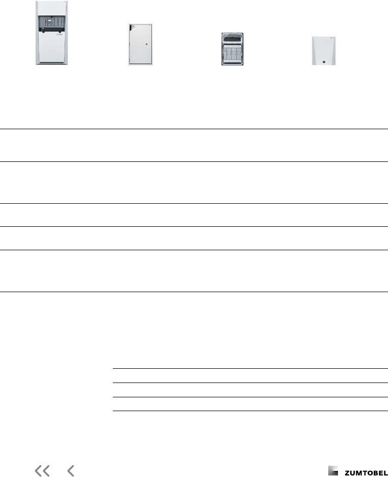
The Lighting Handbook
eBox MS
Main station
eBox MS
Main station
eBox SUB E
Fireproof substation
eBox SUB IP
Substation
eBox SUB IP
Substation
Circuits
(max. luminaires)
ov
erall ( internal,
external for SUB each
with double circuits)
overall ( internal,
external for SUB each
with double circuits)
O
CM m
odules with
outputs circuits per
module
OCM modules with
outputs circuits per
module
OCM modules with
outputs circuits per
module
Maximum number of lumi-
naires depending on the
ava
ilable battery capacity
)
overall
internal
per SUB external
overall
internal
per SUB external
p
cs pcs pcs
Mains connection
-pole (L / N / PE)
/ V
max. VA output in
case of full capacity
-pole (L / N / PE)
/ V
max. VA output in
case of full capacity
-pole (from the main
station L
/ N / PE / B / B-)
-pole (from the main
station L / N / PE / B / B-)
-pole (from the main
station L / N / PE / B / B-)
System Bus connection
two core cable min. x . mm
two core cable
min.
x . mm
two core cable to
main station
two c
ore cable to
main station
two core cable to
main station
Mains operation
Total AC output power
VA per SCM
VA
VA per SCM
VA
VA per SUB
VA per OCM
VA per SUB
VA per OCM
VA per SUB
VA per OCM
Emergency operation
e.g. h duration
Bat
tery output DC total
)
W at Ah
)
accommodated in the cabinet
max. per SCM
W /
W per circuit
W bei Ah
)
accommodated in the cabinet
max. per SCM
W
/ W per circuit
max. W per SUB
)
max. W per circuit
max. W per SUB
)
max. W per circuit
max. W per SUB
)
max. W circuit
Battery voltage V nominal ( – V)
DC output power depends on the available battery capacity
Battery power in W depending on nominal duration of battery-powered operation
)
)
)
Battery type System
voltage
Max. DC system output including ageing reserve as prescribed
by the standard (EN – ..)
ONLITE central eBox
Accu PB
/ [V] h h h h h . h
. Ah
. Ah
. Ah

The Lighting Handbook
ONLITE central eBox – central emergency power supply system
ONLITE central eBox SCM
SCM Switch Connection Module
One ONLITE central eBox SCM is included
in the standard scope of supply. If several
SUB stations are used, one ONLITE central
eBox SCM per SUB station must be ordered
separately.
Output power AC VA
Output power DC W
Fuses ( x mm) x A
Output voltage AC / V
Max. number of luminaires
SCM
Switchover and fuse module
CPU
8AT
8AT
3,15AT
3,15AT
3,15AT
3,15AT
3,15AT
3,15AT
8AT
B-
L
DC
B+
EL1
Circuit 1
Circuit 2
EN1
DALI in
DALI in
EL2
EN2
B-
L
N
AC
AC
DC
N
B+
B-
L
N
B+
DC
AC
Phase
monitoring
Fuse
monitoring
Fuse
monitoring
CPU
ROM
P [W]
P [W]
PLC
3,15AT
3,15AT
3,15AT
3,15AT
3,15AT
3,15AT
EL1
Circuit 1
Circuit 2
EN1
DALI in
DALI out
DALI out
DALI out
DALI out
DALI in
EL2
EN2
AC
DC
B-
L
N
B+
CPU
ROM
P [W]
P [W]
DALI
3,15AT
3,15AT
3,15AT
3,15AT
3,15AT
3,15AT
EL1
Circuit 1
Circuit 2
EN1
EL2
EN2
AC
DC
B-
L
N
B+
CPU
ROM
P [W]
P [W]

The Lighting Handbook
ONLITE central eBox OCM
OCM Output Circuit Modules
Up to three ONLITE central eBox OCMs per
system can be used as an option. In this
context, the dierent functions of the
modules may also be mixed. Each circuit is
separately protected by a . A x mm
fuse. In the battery circuit, there is -pole
fusing, in the mains network -pole fusing.
The total output of the three double-circuit
modules must not exceed VA and
W.
Output power per circuit AC VA
Output power per circuit DC W
Fuses ( x mm) x , A
Output voltage AC / V
Output voltage DC (nominal) V (– V)
OCM-NPS
Double-circuit module
with circuit monitoring
OCM-NSI
Double-circuit module
Powerline communication
OCM-NDA
Double-circuit module
DALI communication
CPU
8AT
8AT
3,15AT
3,15AT
3,15AT
3,15AT
3,15AT
3,15AT
8AT
B-
L
DC
B+
EL1
Circuit 1
Circuit
2
EN1
DALI in
DALI in
EL2
EN2
B-
L
N
AC
AC
DC
N
B+
B-
L
N
B+
DC
AC
Phase
monitoring
Fuse
monitoring
Fuse
monitoring
CPU
ROM
P [W]
P [W]
PLC
3,15AT
3,15AT
3,15AT
3,15AT
3,15AT
3,15AT
EL1
Circuit 1
Circuit 2
EN1
DALI in
DALI out
DALI out
DALI out
DALI out
DALI in
EL2
EN2
AC
DC
B-
L
N
B+
CPU
ROM
P [W]
P [W]
DALI
3,15AT
3,15AT
3,15AT
3,15AT
3,15AT
3,15AT
EL1
Circuit 1
Circuit 2
EN1
EL2
EN2
AC
DC
B-
L
N
B+
CPU
ROM
P [W]
P [W]
CPU
8AT
8AT
3,15AT
3,15AT
3,15AT
3,15AT
3,15AT
3,15AT
8AT
B-
L
DC
B+
EL1
Circuit 1
Circuit 2
EN1
DALI in
DALI in
EL2
EN2
B-
L
N
AC
AC
DC
N
B+
B-
L
N
B+
DC
AC
Phase
monitoring
Fuse
monitoring
Fuse
monitoring
CPU
ROM
P [W]
P [W]
PLC
3,15AT
3,15AT
3,15AT
3,15AT
3,15AT
3,15AT
EL1
Circuit 1
Circuit
2
EN1
DALI in
DALI out
DALI out
DALI out
DALI out
DALI in
EL2
EN2
AC
DC
B-
L
N
B+
CPU
ROM
P [W]
P [W]
DALI
3,15AT
3,15AT
3,15AT
3,15AT
3,15AT
3,15AT
EL1
Circuit 1
Circuit 2
EN1
EL2
EN2
AC
DC
B-
L
N
B+
CPU
ROM
P [W]
P [W]
CPU
8AT
8AT
3,15AT
3,15AT
3,15AT
3,15AT
3,15AT
3,15AT
8AT
B-
L
DC
B+
EL1
Circuit 1
Circuit 2
EN1
DALI in
DALI in
EL2
EN2
B-
L
N
AC
AC
DC
N
B+
B-
L
N
B+
DC
AC
Phase
monitoring
Fuse
monitoring
Fuse
monitoring
CPU
ROM
P [W]
P [W]
PLC
3,15AT
3,15AT
3,15AT
3,15AT
3,15AT
3,15AT
EL1
Circuit 1
Circuit 2
EN1
DALI in
DALI out
DALI out
DALI out
DALI out
DALI in
EL2
EN2
AC
DC
B-
L
N
B+
CPU
ROM
P [W]
P [W]
DALI
3,15AT
3,15AT
3,15AT
3,15AT
3,15AT
3,15AT
EL1
Circuit 1
Circuit
2
EN1
EL2
EN2
AC
DC
B-
L
N
B+
CPU
ROM
P [W]
P [W]

The Lighting Handbook
2 x 3 2 x 52 x 4
1B
2B
L
N
+B
–B
PE
2 x 1
2 x 2
5 (1.5 – 4.0 mm²)
5
3
3
2 (0.75 – 1.5 mm²)
DALI
Powerline
Circuit monitoring
EL1
EN1
PE
DA
DA
EL1
EN1
PE
EL1
EN1
PE
ONLITE central eBox SUB
2 x 3 2 x 52 x 4
1B
2B
L
N
+B
–B
PE
2 x 1
2 x 2
5 (1.5 – 4.0 mm²)
5
3
3
2 (0.75 – 1.5 mm²)
DALI
Powerline
Circuit monitoring
EL1
EN1
PE
DA
DA
EL1
EN1
PE
EL1
EN1
PE
ONLITE central eBox SUB
SUB stations
Cable entry to main station
ONLITE central eBox MS or
ONLITE central eBox MS
ONLITE central eBox – central emergency power supply system

The Lighting Handbook
2 x 3 2 x 52 x 4
1B
2B
L
N
+B
–B
PE
2 x 1
2 x 2
5 (1.5 – 4.0 mm²)
5
3
3
2 (0.75 – 1.5 mm²)
DALI
Powerline
Circuit monitoring
EL1
EN1
PE
DA
DA
EL1
EN1
PE
EL1
EN1
PE
ONLITE central eBox SUB
Cable entry from substation to
main station ONLITE central eBox
The -pole power cable must be installed in a
FP cable up to the place of installation of the
ONLITE central eBox SUB station of the re-
spective re compartment. If several re
compartments are supplied from the ONLITE
central eBox SUB E, the power cable must
be installed in a reproof manner up to the
cabinet, and the nal circuits up to the re
compartments to be supplied in each case.
The system bus may be executed in a lin-
ear manner or in a star topology. Fireproof
installation is not required, since the monitor-
ing of the bus is ensured through heartbeat
control. If on account of an interruption or
short-circuit, any logging data arrive late or
not at all, AC emergency operation of all
lumi naires is activated at the nal circuit.
Three SUB stations
are available
– ONLITE central eBox SUB E
Standard SUB station is used if nal
circuits in dierent re compartments
are served
– ONLITE central eBox SUB E
Standard SUB station in E IP to
supply nal circuits without crossing any
re compartment
– ONLITE central eBox SUB IP
Standard SUB station in E IP to
supply nal circuits without crossing any
re compartment for rough environments
such as industry, car parks or under-
ground parking

The Lighting Handbook
ONLITE central eBox BSIM
max. 9
ONLITE central eBox BPD
max. 9
ONLITE central EPD 2
ONLITE central eBox DSIM
max. 9
L1/N/PE
3
ONLITE central eBox
max. 100 luminaires
Status Address
B1 B2
L N
5
6
7
8
9
0
1
2
3
4
S1 S2 S3 S4
Status
Address
B1 B2
N L1
5
6
7
8
9
0
1
2
3
4
L2 L3
AL1 AL2
out
in
AlarmTest
L
N
DA
DA
in1
L
N
in2
5
6
7
8
9
0
1
2
3
4
Status
Address
L/N
2
S4 – L/N
S3 – L/N
S2 – L/N
S1 – L/N
L1/L2/L3/N
4
L1/L2/L3/N
4
2
ONLITE central eBox
SUB stations
max. 4
ONLITE central eBox
ma x. 600 luminaires
PC / We b browser
Emerge ncy o
System bus
System bus
ma x. 20 luminaires
ma x. 20 luminaires
ma x. 20 luminaires
ma x. 20 luminaires
ma x. 20 luminaires
ma x. 20 luminaires
ONLITE BRI
Betriebsbereit
Ready to operate
Batteriebetrieb
Battery operation
Störung
Failure
L1 N L2 L3
12 11 14 24 21 22
Test
Us
Fault
TCP/IP
Network
DALI
DALI
Individually monitored DALI (NDA)
Individually monitored Powerline (NSI)
Circuit monitored (NPS)
L
N
PE
Individually monitored
System topology
ONLITE BRI remote display
The module is a remote display for
the operational status of an emergen-
cy lighting system. This is required in
every installation under EN .
The remote display is installed at a
superordinate location within the
building, in order to show the status
of the system at any time.
ONLITE central eBox – central emergency power supply system

The Lighting Handbook
ONLITE central eBox BSIM
max. 9
ONLITE central eBox BPD
max. 9
ONLITE central EPD 2
ONLITE central eBox DSIM
max. 9
L1/N/PE
3
ONLITE central eBox
max. 100 luminaires
Status Address
B1 B2
L N
5
6
7
8
9
0
1
2
3
4
S1 S2 S3 S4
Status
Address
B1 B2
N L1
5
6
7
8
9
0
1
2
3
4
L2 L3
AL1 AL2
out
in
AlarmTest
L
N
DA
DA
in1
L
N
in2
5
6
7
8
9
0
1
2
3
4
Status
Address
L/N
2
S4 – L/N
S3 – L/N
S2 – L/N
S1 – L/N
L1/L2/L3/N
4
L1/L2/L3/N
4
2
ONLITE central eBox
SUB stations
max. 4
ONLITE central eBox
ma x. 600 luminaires
PC / We b browser
Emerge ncy o
System bus
System bus
ma x. 20 luminaires
ma x. 20 luminaires
ma x. 20 luminaires
ma x. 20 luminaires
ma x. 20 luminaires
ma x. 20 luminaires
ONLITE BRI
Betriebsbereit
Ready to operate
Batteriebetrieb
Battery operation
Störung
Failure
L1 N L2 L3
12 11 14 24 21 22
Test
Us
Fault
TCP/IP
Network
DALI
DALI
Individually monitored DALI (NDA)
Individually monitored Powerline (NSI)
Circuit monitored (NPS)
L
N
PE
Individually monitored
Status-LED*
Green System is ready for operation
Yellow System in battery mode
Red Too many faulty light sources
in the system
Red
, periodically on/
o every . s
error in the system
A
ll
, o break-down of the system bus
All, periodically
on/o every . s
e
rr
or at the system bus or
main station failure
* Use with ONLITE central eBox

The Lighting Handbook
Ballast/lumen factor table
Emergency
lighting level
Light source
Wattage
AC power
[ ]
V/ Hz
[VA]
DC [W]
DC [W]
DC [W]
DC [W]
DC [W]
DC [W]
DC [W]
DC [W]
DC [W]
DC [W]
Control gear/luminaire
LED .
.
.
.
.
.
.
.
.
.
.
.
.
.
.
.
.
.
.
.
.
.
.
.
.
.
.
.
.
.
.
.
.
.
.
.
.
.
.
.
.
.
.
.
.
.
.
.
.
.
.
.
.
.
.
.
.
.
.
.
.
.
.
.
.
.
.
.
.
.
.
.
.
.
.
.
.
.
.
.
.
.
.
.
.
.
.
.
.
.
.
.
.
.
.
.
.
.
.
.
.
.
.
.
.
.
.
.
.
.
.
.
.
.
.
.
.
.
.
.
.
.
.
.
.
.
.
.
.
.
.
.
.
.
.
E
MpowerX LED NSI / ARTSIGN C EW
EMpowerX LED NSI / ARTSIGN C ED
EMpowerX LED NSI / COMSIGN
EMpowerX LED NSI / CROSSIGN
EMpowerX LED NSI / CROSSIGN ERI
EMpowerX LED NSI / CROSSIGN
EMpowerX LED NSI / CROSSIGN ERI
EMpowerX LED NSI / CUBESIGN
EMpowerX LED NSI / ERGOSIGN LED
EMpowerX LED NSI / ECOSIGN LED IP
EMpowerX LED NSI / FREESIGN
EMpowerX LED NSI / PURESIGN
EMpowerX LED NSI / PURESIGN ERI
EMpowerX LED NSI / RESCLITE C
EMpowerX LED NSI / SQUARESIGN
T W
/ W
W
/ W
W
/ W
W
/ W
W
/ W
W
/ W
W
/ W
W
/ W
W
/ W
.
.
.
.
.
.
.
.
.
.
.
.
.
.
.
.
.
.
.
.
.
.
.
.
.
.
.
.
.
.
.
.
.
.
.
.
.
.
.
.
.
.
.
.
.
.
.
.
.
.
.
.
.
.
.
.
.
.
.
.
.
.
.
.
.
.
.
.
.
.
.
.
.
.
.
.
.
.
.
.
.
.
.
.
.
.
.
.
.
.
.
.
.
.
.
.
.
.
.
.
.
.
.
.
.
.
.
.
.
.
.
.
.
.
.
.
.
.
.
.
.
.
.
.
.
.
.
.
.
.
.
.
.
.
.
.
.
.
.
.
.
.
.
.
.
.
.
.
.
.
.
.
.
.
.
.
.
.
.
.
.
.
.
.
.
.
.
.
.
.
.
.
.
.
.
.
.
.
.
.
.
.
.
.
.
.
.
.
.
.
.
.
.
.
.
.
.
.
P
CA x / T EXCEL oneall lp xitec II
PCA x / T EXCEL oneall lp xitec II
PCA x / T EXCEL oneall lp xitec II
PCA x / T EXCEL oneall lp xitec II
PCA x / T EXCEL oneall lp xitec II
PCA x / T EXCEL oneall lp xitec II
PCA x // T EXCEL oneall lp xitec II
PCA x / T EXCEL oneall lp xitec II
PCA x / T EXCEL oneall lp xitec II
PCA x / T EXCEL oneall lp xitec II
PCA x / T EXCEL oneall lp xitec II
PCA x / T EXCEL oneall lp xitec II
PCA x // T EXCEL oneall lp xitec II
PCA x / T EXCEL oneall lp xitec II
PCA x / T EXCEL oneall lp xitec II
PCA x / T EXCEL oneall lp xitec II
PCA x // T EXCEL oneall lp xitec II
PCA x T EXCEL oneall lp xitec II
T / W
/ W
/ W
/ W
/ W
/ W
.
.
.
.
.
.
.
.
.
.
.
.
.
.
.
.
.
.
.
.
.
.
.
.
.
.
.
.
.
.
.
.
.
.
.
.
.
.
.
.
.
.
.
.
.
.
.
.
.
.
.
.
.
.
.
.
.
.
.
.
.
.
.
.
.
.
P
CA x T EXCEL oneall lp xitec II
PCA x T EXCEL oneall lp xitec II
PCA x T EXCEL oneall lp xitec II
PCA x T EXCEL oneall lp xitec II
PCA x T EXCEL oneall lp xitec II
PCA x T EXCEL oneall lp xitec II
ONLITE central eBox – central emergency power supply system

The Lighting Handbook
Emergency
lighting level
Light source
Wattage
AC power
[ ]
V/ Hz
[VA]
DC [W]
DC [W]
DC [W]
DC [W]
DC [W]
DC [W]
DC [W]
DC [W]
DC [W]
DC [W]
Control gear/luminaire
LED .
.
.
.
.
.
.
.
.
.
.
.
.
.
.
.
.
.
.
.
.
.
.
.
.
.
.
.
.
.
.
.
.
.
.
.
.
.
.
.
.
.
.
.
.
.
.
.
.
.
.
.
.
.
.
.
.
.
.
.
.
.
.
.
.
.
.
.
.
.
.
.
.
.
.
.
.
.
.
.
.
.
.
.
.
.
.
.
.
.
.
.
.
.
.
.
.
.
.
.
.
.
.
.
.
.
.
.
.
.
.
.
.
.
.
.
.
.
.
.
.
.
.
.
.
.
.
.
.
.
.
.
.
.
.
E
MpowerX LED NSI / ARTSIGN C EW
EMpowerX LED NSI / ARTSIGN C ED
EMpowerX LED NSI / COMSIGN
EMpowerX LED NSI / CROSSIGN
EMpowerX LED NSI / CROSSIGN ERI
EMpowerX LED NSI / CROSSIGN
EMpowerX LED NSI / CROSSIGN ERI
EMpowerX LED NSI / CUBESIGN
EMpowerX LED NSI / ERGOSIGN LED
EMpowerX LED NSI / ECOSIGN LED IP
EMpowerX LED NSI / FREESIGN
EMpowerX LED NSI / PURESIGN
EMpowerX LED NSI / PURESIGN ERI
EMpowerX LED NSI / RESCLITE C
EMpowerX LED NSI / SQUARESIGN
T W
/ W
W
/ W
W
/ W
W
/ W
W
/ W
W
/ W
W
/ W
W
/ W
W
/ W
.
.
.
.
.
.
.
.
.
.
.
.
.
.
.
.
.
.
.
.
.
.
.
.
.
.
.
.
.
.
.
.
.
.
.
.
.
.
.
.
.
.
.
.
.
.
.
.
.
.
.
.
.
.
.
.
.
.
.
.
.
.
.
.
.
.
.
.
.
.
.
.
.
.
.
.
.
.
.
.
.
.
.
.
.
.
.
.
.
.
.
.
.
.
.
.
.
.
.
.
.
.
.
.
.
.
.
.
.
.
.
.
.
.
.
.
.
.
.
.
.
.
.
.
.
.
.
.
.
.
.
.
.
.
.
.
.
.
.
.
.
.
.
.
.
.
.
.
.
.
.
.
.
.
.
.
.
.
.
.
.
.
.
.
.
.
.
.
.
.
.
.
.
.
.
.
.
.
.
.
.
.
.
.
.
.
.
.
.
.
.
.
.
.
.
.
.
.
P
CA x / T EXCEL oneall lp xitec II
PCA x / T EXCEL oneall lp xitec II
PCA x / T EXCEL oneall lp xitec II
PCA x / T EXCEL oneall lp xitec II
PCA x / T EXCEL oneall lp xitec II
PCA x / T EXCEL oneall lp xitec II
PCA x // T EXCEL oneall lp xitec II
PCA x / T EXCEL oneall lp xitec II
PCA x / T EXCEL oneall lp xitec II
PCA x / T EXCEL oneall lp xitec II
PCA x / T EXCEL oneall lp xitec II
PCA x / T EXCEL oneall lp xitec II
PCA x // T EXCEL oneall lp xitec II
PCA x / T EXCEL oneall lp xitec II
PCA x / T EXCEL oneall lp xitec II
PCA x / T EXCEL oneall lp xitec II
PCA x // T EXCEL oneall lp xitec II
PCA x T EXCEL oneall lp xitec II
T / W
/ W
/ W
/ W
/ W
/ W
.
.
.
.
.
.
.
.
.
.
.
.
.
.
.
.
.
.
.
.
.
.
.
.
.
.
.
.
.
.
.
.
.
.
.
.
.
.
.
.
.
.
.
.
.
.
.
.
.
.
.
.
.
.
.
.
.
.
.
.
.
.
.
.
.
.
P
CA x T EXCEL oneall lp xitec II
PCA x T EXCEL oneall lp xitec II
PCA x T EXCEL oneall lp xitec II
PCA x T EXCEL oneall lp xitec II
PCA x T EXCEL oneall lp xitec II
PCA x T EXCEL oneall lp xitec II

The Lighting Handbook
Ballast/lumen factor table
ONLITE central eBox – central emergency power supply system
Emergency
lighting level
Light source
Wattage
AC power
[ ]
V/ Hz
[VA]
DC [W]
DC [W]
DC [W]
DC [W]
DC [W]
DC [W]
DC [W]
DC [W]
DC [W]
DC [W]
Control gear/luminaire
TC-L/F / W
/ W
/ W
/ W
/ W
/ W
/ W
/ W
/ W
/ W
.
.
.
.
.
.
.
.
.
.
.
.
.
.
.
.
.
.
.
.
.
.
.
.
.
.
.
.
.
.
.
.
.
.
.
.
.
.
.
.
.
.
.
.
.
.
.
.
.
.
.
.
.
.
.
.
.
.
.
.
.
.
.
.
.
.
.
.
.
.
.
.
.
.
.
.
.
.
.
.
.
.
.
.
.
.
.
.
.
.
.
.
.
.
.
.
.
.
.
.
.
.
.
.
.
.
.
.
.
.
P
CA x / TCL EXCEL oneall c xitec II
PCA x / TCL EXCEL oneall c xitec II
PCA x / TCL EXCEL oneall c xitec II
PCA x / TCL EXCEL oneall c xitec II
PCA x / T EXCEL oneall lp xitec II
PCA x / T EXCEL oneall lp xitec II
PCA x / T EXCEL oneall lp xitec II
PCA x / T EXCEL oneall lp xitec II
PCA x // T EXCEL oneall lp xitec II
PCA x T EXCEL oneall lp xitec II
TC-S/E / W
/ W
.
.
.
.
.
.
.
.
.
.
.
.
.
.
.
.
.
.
.
.
.
.
PCA x / TC EXCEL oneall xitec II
PCA x / TC EXCEL oneall xitec II
TC-D/E / W
/ W
.
.
.
.
.
.
.
.
.
.
.
.
.
.
.
.
.
.
.
.
.
.
PCA x / TC EXCEL oneall xitec II
PCA x / TC EXCEL oneall xitec II
TC-D/T / W
/ W
/ W
/ W
.
.
.
.
.
.
.
.
.
.
.
.
.
.
.
.
.
.
.
.
.
.
.
.
.
.
.
.
.
.
.
.
.
.
.
.
.
.
.
.
.
.
.
.
P
CA x TC EXCEL oneall xitec II
PCA x TC EXCEL oneall xitec II
PCA x - TC EXCEL oneall xitec II
PCA x // TC EXCEL oneall xitec II
TC-T/E / W
/ W
/ W
/ W
.
.
.
.
.
.
.
.
.
.
.
.
.
.
.
.
.
.
.
.
.
.
.
.
.
.
.
.
.
.
.
.
.
.
.
.
.
.
.
.
.
.
.
.
P
CA x - TC EXCEL oneall xitec II
PCA x // TC EXCEL oneall xitec II
PCA x - TC EXCEL oneall xitec II
PCA x // TC EXCEL oneall xitec II
TC-DD
/ W . . . . . . . . . . . PCA x TC-DD EXCEL oneall xitec II

The Lighting Handbook
CPS K
Compact station
CPS H
Main station
CPS U E
Fire-resistant
substation
CPS U E
Substation
Circuits (up to luminaires) ) Up to internal external
) Up to internal external
up to internal external
Maximum number of luminaires ) pcs
)
pcs
pcs
Mains connection -pole x V -pole x V
Mains operation
Total AC output power
– kVA kVA VA VA
Max. AC output power per circuit VA VA VA VA
AC output power per circuits (per UVS) VA VA VA VA
Emergency mode
Total DC output power
. kW [ h]* . kW [ h]* . kW [ h]* kW [ h]*
Max. DC output power per circuit W W
DC output power per circuits (per UVS) W W
Standby operating time – h x V / – Ah
accommodated in
combined cabinet
x V to Ah
accommodated in separate
battery cabinet or battery rack
ONLITE central CPS –
central battery system
Features
– Power in emergency mode – kW
– Up to circuits, each for emergency
luminaires *
– Up to external substations per
main station (CPS H)
– Mixed operation within one circuit
is possible
– Up to (optional) freely assignable
switching inputs
– Web browser-based user interface
System overview
Every ONLITE central CPS oers full function-
ality in order to comprehensively meet the
requirements placed on a central battery
system using as few components as possible.
No additional software or modules are
needed. There is no need to t any separate
components in the luminaire because every
DALI luminaire can be used as an emergency
luminaire which can be individually moni-
tored and controlled. This also reduces eort
on commissioning, inspecting and maintain-
ing the system.
A large removable Touch PC is the core of
the system. For example, it enables straight-
forward commissioning by one person or
neatly laid out, easily manageable visualisa-
tion of the system’s status.

The Lighting Handbook
CPS K
Compact station
CPS H
Main station
CPS U E
Fire-resistant
substation
CPS U E
Substation
Circuits (up to luminaires) ) Up to internal external
) Up to internal external
up to internal external
Maximum number of luminaires ) pcs
)
pcs
pcs
Mains connection -pole x V -pole x V
Mains operation
Total AC output power
– kVA kVA VA VA
Max. AC output power per circuit VA VA VA VA
AC output power per circuits (per UVS) VA VA VA VA
Emergency mode
Total DC output power
. kW [ h]* . kW [ h]* . kW [ h]* kW [ h]*
Max. DC output power per circuit W W
DC output power per circuits (per UVS) W W
Standby operating time – h x V / – Ah
accommodated in
combined cabinet
x V to Ah
accommodated in separate
battery cabinet or battery rack
* Including reserve capacity (battery ageing)

The Lighting Handbook
L1
L2
L3
N
PE
N L3 L2 L1
FI
L1
L2
L3
N
PE
N L3 L2 L1
FI
info
?
<
>
ONLITE central Touch PC
11 14 11 14
+Ub GNDK1 K2 K3
GND 24 V A B
24V
0V
5 x 2
1L
2L
3L
N
EP
4 5 6 7 8 9 10 11 12
3S
2S
4S
5S
6S
7S
+ 1A
– 1A
EP
+ 2A
+
-
+
-
+
-
– 2A
+ xA
– xA
3
3
–
+
3
2
x 12–
ONLITE BRI
Betriebsbereit
Ready to operate
Batteriebetrieb
Battery operation
Störung
Failure
=
~
5 x 1
5 x 1
3
3
2
+1B
–1B
EP
1S
2S
8S
[...]
+1B
–1B
EP
1S
2S
8S
[...]
E60
)tS( YJ Y 8,0 x 2 x 2
)tS( YJ Y 8,0 x 2 x 2
)tS( YJ Y 8,0 x 2 x 2
5 sialeR
6 sialeR
7 sialeR
PE
PE
PE
PE
PE
PE
PE
PE
PE
PE
PE
PE
PE
PE
PE
PE
PE
PE
PE
PE
PE
PE
PE
PE
PE
PE
PE
PE
PE
PE
PE
PE
PE
PE
PE
PE
PE
PE
PE
PE
DALI
DALI
DALI
DALI
DALI
DALI
DALI
DALI
DALI
DALI
DALI
DALI
DALI
DALI
DALI
DALI
DALI
DALI
DALI
DALI
DALI
DALI
DALI
DALI
DALI
DALI
DALI
DALI
DALI
DALI
DALI
DALI
DALI
DALI
DALI
DALI
DALI
DALI
DALI
DALI
L
+ N –
L
+ N –
L
+ N –
L
+ N –
L
+ N –
L
+ N –
L
+ N –
L
+ N –
L
+ N –
L
+ N –
L
+ N –
L
+ N –
L
+ N –
L
+ N –
L
+ N –
L
+ N –
L
+ N –
L
+ N –
L
+ N –
L
+ N –
–2 x 4
HVA
HVS
LE loading unit
Emergency-o
By pressing the emergency-
o button, the complete
ONLITE central CPS system
(including all substations)
is disconnected from power
supply. This ensures that
emergency forces can safely
do their job. The in ternal
V supply is carried via an
NC switch (emergency-o)
and connected to the Ster
-
minal (
x terminal strip at
the main station), while the
conguration is adjusted to
the emergency-o function
using the Touch PC.
Temperature sensor
Fan fault indication
to UVS
to UVS
Mains from HVA
Battery
V
Power supply bus V
System topologygy
ONLITE central CPS – central battery system

The Lighting Handbook
L1
L2
L3
N
PE
N L3 L2 L1
FI
L1
L2
L3
N
PE
N L3 L2 L1
FI
info
?
<
>
ONLITE central Touch PC
11 14 11 14
+Ub GNDK1 K2 K3
GND 24 V A B
24V
0V
5 x 2
1L
2L
3L
N
EP
4 5 6 7 8 9 10 11 12
3S
2S
4S
5S
6S
7S
+ 1A
– 1A
EP
+ 2A
+
-
+
-
+
-
– 2A
+ xA
– xA
3
3
–
+
3
2
x 12–
ONLITE BRI
Betriebsbereit
Ready to operate
Batteriebetrieb
Battery operation
Störung
Failure
=
~
5 x 1
5 x 1
3
3
2
+1B
–1B
EP
1S
2S
8S
[...]
+1B
–1B
EP
1S
2S
8S
[...]
E60
)tS( YJ Y 8,0 x 2 x 2
)tS( YJ Y 8,0 x 2 x 2
)tS( YJ Y 8,0 x 2 x 2
5 sialeR
6 sialeR
7 sialeR
PE
PE
PE
PE
PE
PE
PE
PE
PE
PE
PE
PE
PE
PE
PE
PE
PE
PE
PE
PE
PE
PE
PE
PE
PE
PE
PE
PE
PE
PE
PE
PE
PE
PE
PE
PE
PE
PE
PE
PE
DALI
DALI
DALI
DALI
DALI
DALI
DALI
DALI
DALI
DALI
DALI
DALI
DALI
DALI
DALI
DALI
DALI
DALI
DALI
DALI
DALI
DALI
DALI
DALI
DALI
DALI
DALI
DALI
DALI
DALI
DALI
DALI
DALI
DALI
DALI
DALI
DALI
DALI
DALI
DALI
L
+ N –
L
+ N –
L
+ N –
L
+ N –
L
+ N –
L
+ N –
L
+ N –
L
+ N –
L
+ N –
L
+ N –
L
+ N –
L
+ N –
L
+ N –
L
+ N –
L
+ N –
L
+ N –
L
+ N –
L
+ N –
L
+ N –
L
+ N –
–2 x 4
UVA UVA
UVS
circuit
monitoring
UVS
individual
monitoring
To next UV
System bus
System bus
DALI
Data and Power

The Lighting Handbook
ONLITE central CPS – central battery system
Ballast/lumen factor table
Emergency
lighting level
Light source
Wattage
AC power
[ ]
V/ Hz
[VA]
DC [W]
DC [W]
DC [W]
DC [W]
DC [W]
DC [W]
DC [W]
DC [W]
DC [W]
DC [W]
Control gear/luminaire
LED .
.
.
.
.
.
.
.
.
.
.
.
.
.
.
.
.
.
.
.
.
.
.
.
.
.
.
.
.
.
.
.
.
.
.
.
.
.
.
.
.
.
.
.
.
.
.
.
.
.
.
.
.
.
.
.
.
.
.
.
.
.
.
.
.
.
.
.
.
.
.
.
.
.
.
.
.
.
.
.
.
.
.
.
.
.
.
.
.
.
.
.
.
.
.
.
.
.
.
.
.
.
.
.
.
.
.
.
.
.
.
.
.
.
.
.
.
.
.
.
.
.
.
.
.
.
.
.
.
.
.
.
.
.
.
E
MpowerX LED NSI / ARTSIGN C EW
EMpowerX LED NSI / ARTSIGN C ED
EMpowerX LED NSI / COMSIGN
EMpowerX LED NSI / CROSSIGN
EMpowerX LED NSI / CROSSIGN ERI
EMpowerX LED NSI / CROSSIGN
EMpowerX LED NSI / CROSSIGN ERI
EMpowerX LED NSI / CUBESIGN
EMpowerX LED NSI / ERGOSIGN LED
EMpowerX LED NSI / ECOSIGN LED IP
EMpowerX LED NSI / FREESIGN
EMpowerX LED NSI / PURESIGN
EMpowerX LED NSI / PURESIGN ERI
EMpowerX LED NSI / RESCLITE C
EMpowerX LED NSI / SQUARESIGN
T W
/ W
W
/ W
W
/ W
W
/ W
W
/ W
W
/ W
W
/ W
W
/ W
W
/ W
.
.
.
.
.
.
.
.
.
.
.
.
.
.
.
.
.
.
.
.
.
.
.
.
.
.
.
.
.
.
.
.
.
.
.
.
.
.
.
.
.
.
.
.
.
.
.
.
.
.
.
.
.
.
.
.
.
.
.
.
.
.
.
.
.
.
.
.
.
.
.
.
.
.
.
.
.
.
.
.
.
.
.
.
.
.
.
.
.
.
.
.
.
.
.
.
.
.
.
.
.
.
.
.
.
.
.
.
.
.
.
.
.
.
.
.
.
.
.
.
.
.
.
.
.
.
.
.
.
.
.
.
.
.
.
.
.
.
.
.
.
.
.
.
.
.
.
.
.
.
.
.
.
.
.
.
.
.
.
.
.
.
.
.
.
.
.
.
.
.
.
.
.
.
.
.
.
.
.
.
.
.
.
.
.
.
.
.
.
.
.
.
.
.
.
.
.
.
P
CA x / T EXCEL oneall lp xitec II
PCA x / T EXCEL oneall lp xitec II
PCA x / T EXCEL oneall lp xitec II
PCA x / T EXCEL oneall lp xitec II
PCA x / T EXCEL oneall lp xitec II
PCA x / T EXCEL oneall lp xitec II
PCA x // T EXCEL oneall lp xitec II
PCA x / T EXCEL oneall lp xitec II
PCA x / T EXCEL oneall lp xitec II
PCA x / T EXCEL oneall lp xitec II
PCA x / T EXCEL oneall lp xitec II
PCA x / T EXCEL oneall lp xitec II
PCA x // T EXCEL oneall lp xitec II
PCA x / T EXCEL oneall lp xitec II
PCA x / T EXCEL oneall lp xitec II
PCA x / T EXCEL oneall lp xitec II
PCA x // T EXCEL oneall lp xitec II
PCA x T EXCEL oneall lp xitec II
T / W
/ W
/ W
/ W
/ W
/ W
.
.
.
.
.
.
.
.
.
.
.
.
.
.
.
.
.
.
.
.
.
.
.
.
.
.
.
.
.
.
.
.
.
.
.
.
.
.
.
.
.
.
.
.
.
.
.
.
.
.
.
.
.
.
.
.
.
.
.
.
.
.
.
.
.
.
P
CA x T EXCEL oneall lp xitec II
PCA x T EXCEL oneall lp xitec II
PCA x T EXCEL oneall lp xitec II
PCA x T EXCEL oneall lp xitec II
PCA x T EXCEL oneall lp xitec II
PCA x T EXCEL oneall lp xitec II

The Lighting Handbook
ONLITE central CPS – central battery system
Ballast/lumen factor table
Emergency
lighting level
Light source
Wattage
AC power
[ ]
V/ Hz
[VA]
DC [W]
DC [W]
DC [W]
DC [W]
DC [W]
DC [W]
DC [W]
DC [W]
DC [W]
DC [W]
Control gear/luminaire
TC-L/F / W
/ W
/ W
/ W
/ W
/ W
/ W
/ W
/ W
/ W
.
.
.
.
.
.
.
.
.
.
.
.
.
.
.
.
.
.
.
.
.
.
.
.
.
.
.
.
.
.
.
.
.
.
.
.
.
.
.
.
.
.
.
.
.
.
.
.
.
.
.
.
.
.
.
.
.
.
.
.
.
.
.
.
.
.
.
.
.
.
.
.
.
.
.
.
.
.
.
.
.
.
.
.
.
.
.
.
.
.
.
.
.
.
.
.
.
.
.
.
.
.
.
.
.
.
.
.
.
.
P
CA x / TCL EXCEL oneall c xitec II
PCA x / TCL EXCEL oneall c xitec II
PCA x / TCL EXCEL oneall c xitec II
PCA x / TCL EXCEL oneall c xitec II
PCA x / T EXCEL oneall lp xitec II
PCA x / T EXCEL oneall lp xitec II
PCA x / T EXCEL oneall lp xitec II
PCA x / T EXCEL oneall lp xitec II
PCA x // T EXCEL oneall lp xitec II
PCA x T EXCEL oneall lp xitec II
TC-S/E / W
/ W
.
.
.
.
.
.
.
.
.
.
.
.
.
.
.
.
.
.
.
.
.
.
PCA x / TC EXCEL oneall xitec II
PCA x / TC EXCEL oneall xitec II
TC-D/E / W
/ W
.
.
.
.
.
.
.
.
.
.
.
.
.
.
.
.
.
.
.
.
.
.
PCA x / TC EXCEL oneall xitec II
PCA x / TC EXCEL oneall xitec II
TC-D/T / W
/ W
/ W
/ W
.
.
.
.
.
.
.
.
.
.
.
.
.
.
.
.
.
.
.
.
.
.
.
.
.
.
.
.
.
.
.
.
.
.
.
.
.
.
.
.
.
.
.
.
P
CA x TC EXCEL oneall xitec II
PCA x TC EXCEL oneall xitec II
PCA x - TC EXCEL oneall xitec II
PCA x // TC EXCEL oneall xitec II
TC-T/E / W
/ W
/ W
/ W
.
.
.
.
.
.
.
.
.
.
.
.
.
.
.
.
.
.
.
.
.
.
.
.
.
.
.
.
.
.
.
.
.
.
.
.
.
.
.
.
.
.
.
.
P
CA x - TC EXCEL oneall xitec II
PCA x // TC EXCEL oneall xitec II
PCA x - TC EXCEL oneall xitec II
PCA x // TC EXCEL oneall xitec II
TC-DD
/ W . . . . . . . . . . . PCA x TC-DD EXCEL oneall xitec II

The Lighting Handbook
Chapter
Technology and tables
Protection classes
Degrees of protection
Fire protection
Explosion-proofness
Ball-proofness
IK impact resistance level
Cleanroom technology
Fusing and rating of circuits
Impact on materials
Maintenance of lighting systems
Environmental conditions
Lamp luminous ux maintenance factor (LLMF) and
lamp survival factor (LSF)
Table for luminaire maintenance factor (LMF)
Table for room maintenance factor (RMF)
Table of burning hours

The Lighting Handbook
Protection classes
Protection classes describe measures
providing protection against touch-sensitive
voltages. These measures are set out in the
EN standard and marked with symbols
in compliance with IEC .
Zumtobel luminaires are classied into the
following classes of protection:
Class I luminaires
The luminaire is designed for connection to
a protective conductor.
Protection class I is not identied by a
symbol. The symbol indicating the protective
earth
v is often used.
Unless specied otherwise, all luminaires
by Zumtobel comply at least with protection
class I.
Class II luminaires
Class II luminaires have total insulation but
no protective earth terminal.
The Zumtobel range includes protection
class II luminaires, for instance moisture-
proof batten luminaires and moisture-proof
diuser luminaires.
Class III luminaires
Class III identies luminaires that are
intended for operation with protective extra
low voltage ( V max.).
Architectural luminaires such as
LIGHTMINI and MICROS-S are protection
class III luminaires.
= Protection class I
= Protection class II
= Protection class III
v
w
x

The Lighting Handbook
Degrees of protection
Degrees of protection indicate the following
properties of equipment:
– the quality of its protection against direct
contact
– its sealing against ingress of solid foreign
bodies (dust, stones, sand, etc.)
– its sealing against the ingress of water
The type of protection is dened by two
degrees of protection in accordance with
IEC:
– degree of shock-hazard protection and
protection against ingress of solid foreign
bodies (
st
digit)
– degree of protection against the ingress
of water (
nd
digit)
IP
INGRESS PROTECTION
Protection against ingress of solid foreign bodies
having Ø mm (medium-sized solid bodies),
insertion of ngers or objects.
Protection against ingress of water falling at
any angle up to º from vertical. There must be
no adverse eect (spray water).
Degrees of protection for technical luminaires
Protection against ingress of solid foreign bodies as per rst digit
IPX
IPX
IPX
IPX
IPX
IPX
IPX
Unprotected against ingress of solid foreign bodies
Protection against solid bodies mm
Protection against solid bodies mm
Protection against solid bodies . mm
Protection against solid bodies mm
Dust-protected (limited ingress of dust)
Dust-tight (no ingress of dust)
Protection against moisture as per second digit
IPX
IPX
IPX
IPX
IPX
IPX
IPX
IPX
IPX
No special protection
Drip-proof – protection against water drops
Protection against water drops up to º from the vertical
Rainproof – protection against spray water up to º
Splash-proof – protection against spray water from all directions
Jet-proof – protection against jets of water
Protection against heavy seas (conditions on ship decks)
Watertight – protection against immersion (pressure and time specied)
Protection against immersion under pressure (with instructions from manufacturer)
For example
IP:

The Lighting Handbook
Applications for luminaires with increased protection
Damp locations
Bakeries
Manure sheds
Animal-feed preparation facilities
Industrial kitchens
Boiler rooms
Commercial workshops
Granaries
(Deep-freeze) cold storage
Pump houses
Sculleries
Laundries
IPX
IPX
IPX
IPX
IPX
IP
IPX
IPX
IPX
IPX
IPX
The following generally applies:
IPX: for cleaning using water jets
IPX: in rinsing areas
Wet locations
Beer or wine cellars
Shower cubicles
Meat processing facilities
Electroplating facilities
Greenhouses
Dairies
Workshops using wet processes
Car wash areas
IPX
IPX
IPX
IPX
IPX
IPX
IPX
IPX
The following generally applies:
IPX: for cleaning using water jets
Agricultural facilities
Beer or wine cellars
Shower cubicles
Stores, storerooms for hay, straw, feedstu
Intensive stock farming
Animal sheds
Adjoining rooms of animal sheds
IP
IP
IP
IP
IP
IP
The following generally applies:
IPX: for cleaning using water jets
IPFF: when increased re risk
Facilities with increased re risk
Workrooms
Woodworking
Sawmills
Paper processing
Textile processing
Treatment and fabrication
IP
IP
IP
IP
IP
IP
Gymnasia and sports halls
Badminton courts
Squash courts
Indoor tennis courts
Gymnasia and sports halls
IP
IP
IP
IP
ballproof luminaires
ballproof luminaires with
all-round cover;
maximum mesh size mm

The Lighting Handbook
Fire protection
Luminaires marked with U
This symbol indicates the surface tempera-
ture of luminaire. External surfaces where
highly ammable materials such as dust
or bres may accumulate, even in case of
use according to purpose, must not exceed
specic temperatures.
The
d luminaire mark was withdrawn in
. A period of transition was agreed that
allowed the
d mark to be applied until
//. Since //, the
U mark
introduced by EN has been applied.
The
U mark limits the temperature to
°C max. on horizontal surfaces during
normal operation and to °C in the event
of a ballast fault. On vertical surfaces, °C
must not be exceeded.
Luminaires with the
Q mark
Luminaires which carry the
Qmark are
intend ed for installation in furniture. They are
designed so that in the event of a ballast
fault, ame-retardant and normally amma-
ble materials as specied in DIN cannot
be ignited, e.g. in corners of wooden furni-
ture. The materials may be painted, veneer ed
or varnished.
Luminaires with the
q mark
Luminaires which carry the
q mark are
intend ed for mounting in or on furniture
made of materials whose ammability is not
known. They are designed so that in normal
operation any mounting surface or other
adjacent furniture surfaces do not exceed a
temperature of °C.
Luminaire identication marking
The following criteria must be taken into account:
– position of normal use
– re behaviour of environment and mounting surfaces
– minimum clearance from combustible substances and materials

The Lighting Handbook
Fire protection: Place of use – Mark – Requirements
Place of use Luminaire
mark
Requirements for luminaires
with discharge lamps
Building parts made of non-
combustible building materials
according to DIN Part
as specied in EN
-
Building parts made of ame-
retardant building materials
according to DIN Part
c
as specied in EN - on the mounting surface
Mounting surface
°C
°C
Operation
abnormal
ballast fault
Facilities with increased
re risk according to
DIN VDE Part
U
IPX
as specied in EN -- luminaire surfaces
horizontal
°C
°C
vertical
°C
°C
Operation
normal
abnormal/
ballast fault
Agricultural facilities with
increased re risk according to
DIN VDE Part
DIN VDE Part VDS
/ Form
U
IP
Installation
marking
as specied in EN -- luminaire surfaces
horizontal
°C
°C
vertical
°C
°C
Operation
normal
abnormal/
ballast fault
Installation objects whose re
behaviour is specied as ame
retardant or normally ammable
in DIN Part
Q
Permissive
location
markings
as per DIN VDE Part on the mounting
surface and adjacent surfaces
Mounting surface
°C
°C
Operation
abnormal
ballast fault
Installation objects with
unknown re behaviour
q
Permissive
location
markings
as per DIN VDE Part on the mounting
surface and adjacent surfaces
Mounting surface
°C
°C
°C
Operation
normal
abnormal
ballast fault

The Lighting Handbook
Explosion-proofness b
Flammable gases, vapours and mists
Zone
A hazardous explosive atmosphere is
present continuously or long term.
Zone
A hazardous explosive atmosphere can be
expected to occur occasionally.
Zone
A hazardous explosive atmosphere can be
expected to occur only rarely and, if any,
short term.
Combustible dusts
Zone
Includes areas in which there is a perma-
nent, long-term or frequent explosive at-
mosphere consisting of dust-air mixtures.
Zone
Includes areas in which an explosive
atmosphere consisting of dust-air mixtures
can be expected to occur occasionally and
short term.
Zone
Includes areas in which an explosive
atmosphere cannot be expected to occur
due to disturbance of deposited dust. If an
explosive atmosphere should nevertheless
occur, this will most probably happen only
rarely and short term.
Directive 94/9/EC
Directive //EC species the requirements
for all devices and protection systems for
use in explosion-prone areas. Over and
above this, this Directive now directly
includes the “Basic safety requirements” for
explosion-proof equipment.
Manufacturers of explosion-proof
equipment have to provide evidence of a
quality assurance system to be tested by a
“notied body”.
Directive 99/92 EC (Workplace Directive)
Also important is the description of hazard
areas in explosion-prone workplaces, and a
resulting graded safety prole for the
“equipment” used.
As this Directive was drafted according
to the EC’s “new approach”, the manu-
facturer’s declaration of conformity, com-
bined with CE marking of the products,
was introduced for explosion-proof equip-
ment as well.
A detailed commentary on Directive
//EC is included in the “Directive //EC
by the European Parliament and the Council
of March ” section. Since July ,
it has superseded all directives on explosion
protection previously eective at European
level.

The Lighting Handbook
Equipment of Group 2 including potential ignition source
Classication of max. surface temperatures in
electrical equipment of Class
Equipment cat. Equipment cat. Equipment cat.
EC type examination
Documentation
of notified body
Internal production control
Documentation
of manufacturer
Electrical appliance
Engine with internal
combustion
Yes No
Basic safety and health requirements
Temperature class Max. permissible
surface temperature
of equipment in °C
Ignition temperatures
of ammable substances
in °C
T
T
T
T
T
T

The Lighting Handbook
Ball-proofness
Luminaires for sports halls must be ball-proof according to
DIN VDE -.
Balls hitting luminaires must not damage them so as to
cause luminaire parts to fall down. In a test conforming with
the relevant standard, the luminaire has to withstand hits
from three directions at a maximum impact speed of
km/h, the ball used having the size of a handball.
When choosing the luminaires, the rod guard’s grid width
must be matched to the sport played in the hall: it must
always be considerably smaller than the balls used, never of
the same size, as balls may get stuck in the guard.

The Lighting Handbook
IK impact resistance level
The IK impact resistance level or IK degree of
protection is a measure of the resistance of
enclosures for electrical control gear against
mechanical stress. The international standard
IEC (corresponds to EN ) lists
degrees of protection:
Degree of
protection
Impact energy
(Joule)
IK No impact resistance
IK Up to .
IK Up to .
IK Up to .
IK Up to .
IK Up to .
IK Up to .
IK Up to .
IK Up to .
IK Up to .
IK Up to .
This provides information about the impact
energy, which an enclosure can withstand
without breaking. One can expect the follow-
ing maximum loads in practice:
– up to IK: blows with the hand or st
– IK: blows with a g hammer
from a distance of cm
– IK: blows with a g hammer
from a distance of cm
– IK: blows with a . kg hammer
from a distance of cm
– IK: blows with a kg hammer
from a distance of cm
– IK: blow with a baseball bat,
projectiles, kicks

The Lighting Handbook
Cleanroom technology
Cleanroom compatibility tested
CLEAN Advanced and CLEAN Supreme
have been tested and assessed by the
Fraunhofer Institute in Stuttgart (Germany)
with respect to
– cleanroom compatibility for cleanrooms
(particle emission behaviour of the
luminaires) and
– cleanliness compatibility (disinfectability,
electrostatic behaviour and chemical
resistan ce).
Details on cleanroom compatibility
The German VDI Guideline species
a standardised procedure for all equipment
used in a cleanroom.
The common criterion for the cleanroom
compatibility of luminaires and all other
equipment is their particle emission behav-
iour. “Airborne particle emission” is used as
a classication criterion in all international
standards. The relevant maximum value for
the permissible concentration of particles
of a specic particle size constitutes the
class limit.
Test setup
A dened volume of air is aspirated by an air
sampling probe and fed into a test chamber.
The particles inside this test chamber are
monitored and recorded appropriately.
Exceeding the relevant limit values is deci-
sive in order to classify the luminaires. If a
limit value is not exceeded with a certainty of
at least , the respective item of equip-
ment may be regarded as suitable for use in
this air cleanliness class.
Details on cleanliness compatibility
In order to be able to conrm cleanliness
compatibility, as well as, quantities reecting
cleanroom compatibility that can be de tected
by metrological methods, additional expert
assessments and parameters were included
in the tests conducted by the Fraunhofer
Institute IPA.
Cleanliness compatibility covers a large
number of sector-based cleanliness require-
ments such as resistance to chemicals, sur-
face quality, ow behaviour or electro static
charge characteristics. These are dened in
the following standards and codes of practice,
among others:

The Lighting Handbook
Standardisation
General:
– classication of air cleanliness –
clean-rooms and associated controlled
environments according to DIN EN ISO
- (Federal Standard has been
withdrawn)
– cleanroom technology and cleanroom
compatibility of equipment VDI
– EHEDG (European Hygienic Engineering
& Design Group)
Industrial application areas:
– GMP Guidelines (Good Manufacturing
Practice) – pharmaceuticals
– FDA (Food and Drug Administration) –
pharmaceuticals and foodstus
– Medicinal Product Law
– EU Pharmaceutical Regulation – Good
manufacturing practices Volume –
(Medicinal products for human and
veterinary use)
– Hazard Analytical Control Point (HACCP)
Regulations – foodstus
Hospital application areas:
– VDI Building services in hospitals
– DIN - Ventilation and air conditioning
Part (Ventilation in hospitals)
Airow systems in cleanrooms
One of the basic criteria for the requirements
placed on equipment in cleanrooms is the
nature of the airow system. The CLEAN
luminaire has been designed for use in all
cleanroom classes with a turbulent mixed
airow. In this commonly encountered airow
system, air enters the room with a turbulent
ow, thereby causing continuous dilution and
“cleaning”. According to GMP (Good
Manufacturing Practice) classication, clean-
room Classes C to E and ISO Classes to
can be achieved using this airow system.
Cleanrooms with low-turbulence displace-
ment ow, which are more expensive to build,
allow air to initially enter the cleanroom with
low turbulence. The design of laminar ow
cleanrooms precludes the use of any lumi-
naires other than extremely slim batten
luminaires which disrupt the direct ional ow
of air as little as possible. The laminar ow
system minimises contamination, and any
contaminant is quickly eliminated. Clean-
rooms in ISOClasses to and GMP Classes
A and B are areas where this airow system
is used.

The Lighting Handbook
Fusing and rating of circuits
Tripping values of line circuit-breakers
For the operation of luminaires, automatic
circuit breakers with C characteristics are
recommended. In case of multipolar circuit
breakers, the values specied by the manu-
facturer must be reduced by . The
levels indicated in the table refer to simulta-
neous switch-on at the mains voltage peak
with UN V.
Please note: the values given in the table
are intended as reference values only and
may deviate in individual cases. The specic
range and type, as well as, the actual number
of ballasts per luminaire must be taken into
account. In case of metal halide lamps, the
switch-on current is increased by ignition
time shunting. In case of connection to circuit
breakers with B characteristics, transformers
should not be loaded above rating in order to
avoid false tripping.
Tripping characteristics Tripping current
B (quick-acting)
C
to -fold rated current
to -fold rated current

The Lighting Handbook
Loading of automatic circuit breakers for metal halide lamps –
maximum recommended number of electronic ballasts per automatic circuit breaker
Loading of automatic circuit breakers for electronic ballasts for uorescent and
compact uorescent lamps – maximum recommended number of electronic ballasts
per automatic circuit breaker
C C C C B B B B
mm
. . . . . . . .
/ W HI
/ W HI
/ W HI
/ W HI
Electronic ballasts for T uorescent lamps, not dimmable
(TRIDONIC PC T PRO range):
Electronic ballasts for HIT/HIT-DE/HIE and
HIT-CE/HIT-TC-C²E/HIT-DE-CE/HIE-CE metal halide lamps, non-dimmable (TRIDONIC PCI range):
C C C C B B B B
mm
. . . . . . . .
/ W T
/ W T
/ W T
/ W T
/ W T
/ W T
/ W T
/ W T
/ W T
/ W T
/ W T
/ W T
/ W T
/ W T
/ W T
/ W T
/ W T
/ W T
/ W T

The Lighting Handbook
Electronic ballasts for T uorescent lamps, Basic dimmable/DALI-dimmable
(TRIDONIC PCA T ECO/PCA T EXCEL oneall ranges):
Electronic ballasts for T uorescent lamps, non-dimmable
(TRIDONIC PC E/PC T PRO ranges):
Fusing and rating of circuits
C C C C B B B B
mm
. . . . . . . .
/ W T
/ W T
/ W T
/ W T
/ W T
/ W T
/ W T
/ W T
/ W T
/ W T
/ W T
/ W T
/ W T
/ W T
/ W T
/ W T
/ W T
C C C C B B B B
mm
. . . . . . . .
/ W T / / / / / / / /
/ W T / / / / / / / /
/ W T /– /– /– /– /– /– /– /–
/ W T /– /– /– /– /– /– /– /–
/ W T / / / / / / / /
/ W T / / / / / / / /
/ W T / / / / / / / /
/ W T / / / / / / / /
Loading of automatic circuit breakers for electronic ballasts for uorescent and
compact uorescent lamps – maximum recommended number of electronic ballasts
per automatic circuit breaker

The Lighting Handbook
Electronic ballasts for T uorescent lamps, Basic dimmable/DALI-dimmable
(TRIDONIC PCA T ECO/PCA T EXCEL oneall ranges):
Electronic ballasts for TC-L compact uorescent lamps, Basic dimmable/DALI-dimmable
(TRIDONIC PCA TCL ECO/PCA TCL EXCEL oneall ranges):
C C C C B B B B
mm
. . . . . . . .
/ W TC-L
/ W TC-L
/ W TC-L
/ W TC-L
/ W TC-L
/ W TC-L
/ W TC-L
/ W TC-L
/ W TC-L
/ W TC-L
/ W TC-L
C C C C B B B B
mm
. . . . . . . .
/ W T
/ W T
/ W T
/ W T
/ W T
/ W T
/ W T
/ W T
/ W T
/ W T

The Lighting Handbook
Electronic ballasts for TC-DEL/TEL uorescent lamps, non-dimmable
(TRIDONIC PC PRO range):
Fusing and rating of circuits
Electronic ballasts for TC-L compact uorescent lamps, non-dimmable
(TRIDONIC PC PRO FSD ranges):
C C C C B B B B
mm
. . . . . . . .
/ W TC-L
/ W TC-L
/ W TC-L
/ W TC-L
/ W TC-L
/ W TC-L
/ W TC-L
/ W TC-L
/ W TC-L
/ W TC-L
/ W TC-L
C C C C B B B B
mm
. . . . . . . .
/ W TC-DEL/TC-TEL
/ W TC-DEL/TC-TEL
/ W TC-DEL/TC-TEL
/ W TC-DEL/TC-TEL
/ W TC-DEL/TC-TEL
/ W TC-DEL/TC-TEL
/ W TC-TEL
/ W TC-TEL
/ W TC-TEL
/ W TC-TEL
/ W TC-TEL
Loading of automatic circuit breakers for electronic ballasts for uorescent and
compact uorescent lamps – maximum recommended number of electronic ballasts
per automatic circuit breaker

The Lighting Handbook
Electronic ballasts for TC-DEL/TEL compact uorescent lamps Basic dimmable/DALI-dimmable
(TRIDONIC PCA ECO/PCA EXCEL oneall ranges):
C C C C B B B B
mm
. . . . . . . .
/ W TC-DEL/TC-TEL
/ W TC-DEL/TC-TEL
/ W TC-DEL/TC-TEL
/ W TC-DEL/TC-TEL
/ W TC-DEL/TC-TEL
/ W TC-DEL/TC-TEL
/ W TC-TEL
/ W TC-TEL
/ W TC-TEL
/ W TC-TEL

The Lighting Handbook
Loading of automatic circuit breakers for low-voltage halogen
incandescent lamps – maximum recommended number of transformers
per automatic circuit breaker
Magnetic transformers for
QT/QR/QR-CB(C) halogen incandescent lamps
(TRIDONIC TMBx/OMTx ranges):
Magnetic transformers for
QT/QR/QR-CB(C) halogen incandescent lamps
(TRIDONIC OGT range):
Magnetic transformers for
QT/QR/QR-CB(C) halogen incandescent lamps
(TRIDONIC TMAx/TMDx ranges):
Fusing and rating of circuits
C C B B
W
W
W
W
W
W
W – –
W – – n.r.
C C B B
W – – – –
W – –
W – n.r. n.r.
C C B B
W
W
W
W
W
W
W
W
n.r. not recommended
n.r. not recommended

The Lighting Handbook
Automatic circuit breaker ratings for LED downlights and spotlights –
maximum number of DLs recommended per automatic circuit breaker
The type of automatic circuit breakers and
the corresponding maximum number of
luminaires are specied in Zumtobel’s online
catalogue. Moreover, the LED luminaire’s
switch-on current and pulse width are also
indicated at the bottom of the table.
Information about automatic circuit breakers
is available at the respective product page
under:
zumtobel.com/com-en/products

The Lighting Handbook
Impact on materials
No material is resistant to all chemical inu-
ences. This is not really surprising, as there
are so many chemicals and so many eects;
in fact, they ll whole volumes with resist-
ance tables.
When assessing potential hazards, the
degree of saturation of chemical substances
and the ambient temperature must be taken
into account.
The accompanying tables therefore only
provide a brief overview of frequently en-
countered applications and chemical impact.
If you are unsure or have specic ques-
tions, your Zumtobel adviser will be happy
to assist.
Excellent properties
Recommendations according to application area
PC PMMA CHEMO Polyester
IK code
UV resistance **
Shock resistance Nm . Nm Nm . Nm
Resistance to ageing *
Silicone-free Yes Yes Yes Yes
Halogen-free Yes Yes Yes Yes
International Food Standards (IFS) certication Yes Yes Yes Yes
Glow-wire tested °C °C °C °C
Heat resistance of luminaire plastics °C °C* °C
Flammability acc. to UL (ISO ) V HB HB HB
UV transmittance
* limited UV stability of PC ** UV stabilised
PC PMMA CHEMO
Damp locations
Bake houses
Damp cellars –
Fodder kitchens
Large-scale catering establishments
highly recommended suitable – unsuitable ➝ to be continued on the next page
* with plastic catches and special ceiling brackets (available on request)

The Lighting Handbook
PC PMMA CHEMO
Wet locations
Beer and wine cellars
Breweries –
Wine cellars (using sulphur to steam out barrels) –
Damp pump rooms
Meat-processing facilities –
Electroplating plants (caution: do not use VA) – * *
Conservatories
Cheese dairies –
Dairies –
Washing bays/car washes (motor vehicles) –
Rooms or areas in bathhouses or laundries
Bathrooms/shower rooms
Thermal spas and brine baths
Agricultural premises
Fodder preparation
Greenhouses
Storage areas/storerooms for hay, straw, fodder, fertilisers
Areas for animal husbandry (stables) –
Locations exposed to re hazards (only version with electronic ballast is re resistant)
Woodworking
Paper processing –
Textile processing plants –
Theatre workshops
Drying rooms
Garages
Underground garages
Car parks
Private garages
Vehicle depots
Outdoor facilities
Facilities on ramps (canopied)
Gateways (canopied)
Canopied railway platforms
Canopied petrol stations
Canopy roofs
Recommendations according to application area

The Lighting Handbook
Impact on materials
Chemical resistance of materials
PC PMMA CHEMO Polyester
Acetic acid up to
Acetic acid up to
– –
Acetone – –
–
Aliphatic hydrocarbons
Ammonia –
Aniline – – – –
Aromatic hydrocarbons – –
Battery acid
Beer
Benzene – –
–
Blood
Bromic acid – – – –
Carbon dioxide
Carbon monoxide
Carbon tetrachloride – –
Caustic potash solution –
–
Chloroform – –
–
Chlorophenol – – – –
Cleaner’s naphtha (solvent)
Cresol – – – –
Dichloromethane – –
–
Diesel fuel –
Diesel oil, crude oil
Dimethyl benzene – –
–
Dioxane – –
Ethanol
Ethanol
–
Ether – –
Ethyl acetate – –
–
Fats: animal –
Fats: mineral –
Fats: vegetable –
Four-star petrol – –
Fuel oil –
Glycerol
resistant – not resistant
The information given is valid under the following conditions: the chemical substance listed in the table is a
basic ma terial and not part of a chemical compound. The ambient temperature is °C.

The Lighting Handbook
resistant – not resistant
PC PMMA CHEMO Polyester
Glycol
Glysantin
®
Hydrochloric acid (HCl)
Hydrochloric acid (HCl)
–
Hydrogen peroxide over
–
–
Hydrogen peroxide up to
–
Hydrogen sulphide
Isopropyl alcohol
–
Ketones – –
–
Methyl alcohol – –
–
Milk of lime
Nitric acid over – – – –
Nitric acid up to
–
Nitric acid up to
–
Petroleum ether
Phenol – – – –
Pyridine – –
–
Regular petrol
–
Seawater
Silicone oil
Soapsuds
Soda
Sodium hydroxide solution –
Sodium hydroxide solution –
–
Solution of sodium chloride
Spirit of turpentine
Sulphuric acid (HSO)
Sulphuric acid (HSO)
–
Sulphuric acid (HSO) – – – –
Sulphuric acid (HSO) – – – –
Sulphurous acid up to –
Synthetic detergent solution
Toluene – –
–
Trichloroethane – –
Water up to °C
The information given is valid under the following conditions: the chemical substance listed in the table is a
basic ma terial and not part of a chemical compound. The ambient temperature is °C.

The Lighting Handbook
Maintenance of lighting systems
Today, the maintenance of lighting installa-
tions is a decisive factor in an installation’s
balance of costs.
According to the formula below (), a light-
ing level required of E
m
lx at a standard
maintenance factor of MF . implies a
new illuminance level of E
new
lx.
E
m
: maintained illuminance
maintenance value of illuminance
() E
m
E
new
x MF Maintenance factor components
– Lamp luminous ux mainten. factor LLMF
– Lamp survival factor LSF
– Luminaire maintenance factor LMF
– Room maintenance factor RMF
Causes of illuminance decrease
– Ageing of lamps
– Failure of lamps
– Soiling of luminaire
– Soiling of room
The maintenance factor includes
4 components
() MF LLMF x LSF x LMF x RMF
Benet of a high MF
– lower luminaire investment costs
– reduced energy costs
Benet of a low MF
– low maintenance costs
– longer maintenance intervals
Please note: at a lower maintenance factor,
illuminance may be constantly dimmed to the
maintenance value to save energy (maintenance
control).
All these factors describe the decrease in
illumi nance. The maximum in each case is ,
corresponding to the new value. At the
respec tive time of maintenance, the various
causes of the decrease in illuminance must
be identied.
Options for improving the
maintenance factor
– lamp replacement already before the lamp
service life ends (LLMF/LSF )
– immediate replacement of lamps in case
of failure (LSF )
– use of closed luminaires (LWF )
– more frequent room cleaning (RWF )
➝
➝
➝

The Lighting Handbook
Ambient
condition
Maintenance interval
recommended
Working areas Reference main-
tenance factor
Very Clean (VC) years Cleanrooms, data centres,
assembly workstations for
electronic components
.
Clean (C) years Oces
Schools
.
Normal (N) years Shops
Laboratories
Restaurants
Warehouses
Assembly bays
.
Soiled (S) year Steel works
Chemical plants
Foundries
Welding shops
Grinding shops
Wood processing
.
According to CIE – volume , “Maintenance of indoor electric lighting systems”, as at
In case you are not familiar with the appli cation, the following standard
values apply; however, the tables below will help you calcu late the accurate
maintenance factor according to formula ().
. . . . . . .
Example:
Luminaire maintenance: every year
Room surface maintenance: every years
Lamp replacement: every years
Faulty lamp replacement: immediately
E
m
E
new
years
Environmental conditions

The Lighting Handbook
Lamps Service life given in hours
Halogen incandescent lamp
CIE:
LLMF
LSF
.
.
.
.
.
.
.
.
T (low-loss ballast) triple-band uor. lamp
ZVEI
LLMF
LSF
.
.
.
.
.
.
.
.
.
.
.
.
.
.
.
.
.
.
.
.
.
.
T (electronic ballast) triple-band uor. lamp
ZVEI /CIE:
LLMF
LSF
.
.
.
.
.
.
.
.
.
.
.
.
.
.
.
.
.
.
.
.
.
.
.
.
.
.
.
.
T (electronic ballast) triple-band uor. lamp, long-life
Philips MASTER TL-D Xtreme (long life)
LLMF
LSF
.
.
.
.
.
.
.
.
.
.
.
.
.
.
.
.
.
.
.
.
.
.
.
.
.
.
.
.
.
.
.
.
.
.
.
.
.
.
.
.
T (electronic ballast) triple-band uor. lamp, long-life
AURA Ultimate LL (long life)
LLMF
LSF
.
.
.
.
.
.
.
.
.
.
.
.
.
.
.
.
.
.
.
.
.
.
.
.
.
.
.
.
.
.
.
.
.
.
.
.
.
.
.
.
T (electronic ballast) triple-band
ZVEI
LLMF
LSF
.
.
.
.
.
.
.
.
.
.
.
.
.
.
.
.
.
.
.
.
.
.
.
.
.
.
.
.
.
.
.
.
T (electronic ballast) triple-band uor. lamp, long-life
AURA SUPREME T HO LL (long life)
LLMF
LSF
.
.
.
.
.
.
.
.
.
.
.
.
.
.
.
.
.
.
.
.
.
.
.
.
.
.
.
.
.
.
.
.
.
.
.
.
.
.
.
.
Compact uorescent lamp
CIE:
LLMF
LSF
.
.
.
.
.
.
.
.
.
.
.
.
.
.
.
.
TC-S, TC-D, TC-T – W (low-loss ballast)
Compact uorescent lamp
ZVEI
LL
MF
LSF
.
.
.
.
.
.
.
.
.
.
.
.
.
.
.
.
.
.
TC-SEL, TC-TEL – W (electronic ballast)
Compact uorescent lamp
ZVEI
LL
MF
LSF
.
.
.
.
.
.
.
.
.
.
.
.
.
.
.
.
.
.
.
.
TC-DEL – W (electronic ballast)
Compact uorescent lamp
ZVEI
LL
MF
LSF
.
.
.
.
.
.
.
.
.
.
.
.
.
.
.
.
.
.
.
.
.
.
TC-L – W (low-loss ballast)
Compact uorescent lamp
ZVEI
LL
MF
LSF
.
.
.
.
.
.
.
.
.
.
.
.
.
.
.
.
.
.
.
.
.
.
TC-L – W (electronic ballast)
Compact uorescent lamp
ZVEI
LL
MF
LSF
.
.
.
.
.
.
.
.
.
.
.
.
.
.
.
.
.
.
.
.
.
.
.
.
.
.
.
.
Values acc. to specications by lamp manufacturers, January , acc. to CIE:
Technical report “Guide on the Maintenance of Indoor Electric Lighting Systems” nd edition, and ZVEI publication
“Service life behaviour of discharge lamps for lighting” of November .
For data of lamps by other manufacturers or other lamp types, please contact the respective manufacturer directly.
The use of state-of-the-art ballast technology is a prerequisite.
The switching frequency has a major inuence on lamp survival.
Most data are based on the standardised -hour switching rhythm acc. to IEC (. h ON, . h OFF).
Lamp luminous ux maintenance factor (LLMF)
and lamp survival factor (LSF)
Maintenance of lighting systems

The Lighting Handbook
Lamps Service life given in hours
Halogen incandescent lamp
CIE:
LLMF
LSF
.
.
.
.
.
.
.
.
T (low-loss ballast) triple-band uor. lamp
ZVEI
LLMF
LSF
.
.
.
.
.
.
.
.
.
.
.
.
.
.
.
.
.
.
.
.
.
.
T (electronic ballast) triple-band uor. lamp
ZVEI /CIE:
LLMF
LSF
.
.
.
.
.
.
.
.
.
.
.
.
.
.
.
.
.
.
.
.
.
.
.
.
.
.
.
.
T (electronic ballast) triple-band uor. lamp, long-life
Philips MASTER TL-D Xtreme (long life)
LLMF
LSF
.
.
.
.
.
.
.
.
.
.
.
.
.
.
.
.
.
.
.
.
.
.
.
.
.
.
.
.
.
.
.
.
.
.
.
.
.
.
.
.
T (electronic ballast) triple-band uor. lamp, long-life
AURA Ultimate LL (long life)
LLMF
LSF
.
.
.
.
.
.
.
.
.
.
.
.
.
.
.
.
.
.
.
.
.
.
.
.
.
.
.
.
.
.
.
.
.
.
.
.
.
.
.
.
T (electronic ballast) triple-band
ZVEI
LLMF
LSF
.
.
.
.
.
.
.
.
.
.
.
.
.
.
.
.
.
.
.
.
.
.
.
.
.
.
.
.
.
.
.
.
T (electronic ballast) triple-band uor. lamp, long-life
AURA SUPREME T HO LL (long life)
LLMF
LSF
.
.
.
.
.
.
.
.
.
.
.
.
.
.
.
.
.
.
.
.
.
.
.
.
.
.
.
.
.
.
.
.
.
.
.
.
.
.
.
.
Compact uorescent lamp
CIE:
LLMF
LSF
.
.
.
.
.
.
.
.
.
.
.
.
.
.
.
.
TC-S, TC-D, TC-T – W (low-loss ballast)
Compact uorescent lamp
ZVEI
LL
MF
LSF
.
.
.
.
.
.
.
.
.
.
.
.
.
.
.
.
.
.
TC-SEL, TC-TEL – W (electronic ballast)
Compact uorescent lamp
ZVEI
LL
MF
LSF
.
.
.
.
.
.
.
.
.
.
.
.
.
.
.
.
.
.
.
.
TC-DEL – W (electronic ballast)
Compact uorescent lamp
ZVEI
LL
MF
LSF
.
.
.
.
.
.
.
.
.
.
.
.
.
.
.
.
.
.
.
.
.
.
TC-L – W (low-loss ballast)
Compact uorescent lamp
ZVEI
LL
MF
LSF
.
.
.
.
.
.
.
.
.
.
.
.
.
.
.
.
.
.
.
.
.
.
TC-L – W (electronic ballast)
Compact uorescent lamp
ZVEI
LL
MF
LSF
.
.
.
.
.
.
.
.
.
.
.
.
.
.
.
.
.
.
.
.
.
.
.
.
.
.
.
.
Values acc. to specications by lamp manufacturers, January , acc. to CIE:
Technical report “Guide on the Maintenance of Indoor Electric Lighting Systems” nd edition, and ZVEI publication
“Service life behaviour of discharge lamps for lighting” of November .
For data of lamps by other manufacturers or other lamp types, please contact the respective manufacturer directly.
The use of state-of-the-art ballast technology is a prerequisite.
The switching frequency has a major inuence on lamp survival.
Most data are based on the standardised -hour switching rhythm acc. to IEC (. h ON, . h OFF).

The Lighting Handbook
Lamps Service life given in hours
Metal halide lamp Ceramic (– W)
CIE:
LLMF
LSF
.
.
.
.
.
.
.
.
.
.
.
.
.
.
.
.
.
.
Metal halide lamp Ceramic
Philips CDM-T W/Elite
LLMF
LSF
.
.
.
.
.
.
.
.
.
.
.
.
.
.
.
.
.
.
.
.
Metal halide lamp Ceramic
Osram HCI-T W/WDL PB
LLMF
LSF
.
.
.
.
.
.
.
.
.
.
.
.
.
.
.
.
.
.
.
.
Metal halide lamp Ceramic
Osram HCI W PB
LLMF
LSF
.
.
.
.
.
.
.
.
.
.
.
.
.
.
.
.
.
.
.
.
Metal halide lamp Quartz (/ W)
CIE:
LLMF
LSF
.
.
.
.
.
.
.
.
.
.
.
.
.
.
.
.
.
.
.
.
.
.
.
.
.
.
Metal halide lamp Quartz
Osram HQI-E W/D
LLMF
LSF
.
.
.
.
.
.
.
.
.
.
.
.
.
.
.
.
.
.
.
.
Metal halide lamp Quartz
Osram HQI-E W/D
LLMF
LSF
.
.
.
.
.
.
.
.
.
.
.
.
.
.
.
.
.
.
.
.
Metal halide lamp Quartz
Osram HQI-BT W/N
LLMF
LSF
.
.
.
.
.
.
.
.
.
.
.
.
.
.
.
.
.
.
.
.
Metal halide lamp Quartz
Philips HPI-T Plus / W
LLMF
LSF
.
.
.
.
.
.
.
.
.
.
.
.
.
.
.
.
.
.
.
.
.
.
.
.
.
.
.
.
Sodium vapour lamp / W
ZVEI
LLMF
LSF
.
.
.
.
.
.
.
.
.
.
.
.
.
.
.
.
.
.
.
.
.
.
.
.
.
.
.
.
.
.
Sodium vapour lamp – W (standard lum. ux level)
ZVEI
LLMF
LSF
.
.
.
.
.
.
.
.
.
.
.
.
.
.
.
.
.
.
.
.
.
.
.
.
.
.
.
.
.
.
.
.
Sodium vapour lamp – W (increased lum. ux level)
ZVEI
LLMF
LSF
.
.
.
.
.
.
.
.
.
.
.
.
.
.
.
.
.
.
.
.
.
.
.
.
.
.
.
.
.
.
.
.
Sodium vapour lamp
Philips SON(-T) PIA Plus – W
LLMF
LSF
.
.
.
.
.
.
.
.
.
.
.
.
.
.
.
.
.
.
.
.
.
.
.
.
.
.
.
.
.
.
.
.
.
.
.
.
Values acc. to specications by lamp manufacturers, January , acc. to CIE:
Technical report “Guide on the Maintenance of Indoor Electric Lighting Systems” nd edition, and ZVEI publication
“Service life behaviour of discharge lamps for lighting” of November .
For data of lamps by other manufacturers or other lamp types, please contact the respective manufacturer directly.
The use of state-of-the-art ballast technology is a prerequisite.
The switching frequency has a major inuence on lamp survival.
Most data are based on the standardised -hour switching rhythm acc. to IEC (. h ON, . h OFF).
Lamp luminous ux maintenance factor (LLMF)
and lamp survival factor (LSF)
Maintenance of lighting systems

The Lighting Handbook
Lamps Service life given in hours
Metal halide lamp Ceramic (– W)
CIE:
LLMF
LSF
.
.
.
.
.
.
.
.
.
.
.
.
.
.
.
.
.
.
Metal halide lamp Ceramic
Philips CDM-T W/Elite
LLMF
LSF
.
.
.
.
.
.
.
.
.
.
.
.
.
.
.
.
.
.
.
.
Metal halide lamp Ceramic
Osram HCI-T W/WDL PB
LLMF
LSF
.
.
.
.
.
.
.
.
.
.
.
.
.
.
.
.
.
.
.
.
Metal halide lamp Ceramic
Osram HCI W PB
LLMF
LSF
.
.
.
.
.
.
.
.
.
.
.
.
.
.
.
.
.
.
.
.
Metal halide lamp Quartz (/ W)
CIE:
LLMF
LSF
.
.
.
.
.
.
.
.
.
.
.
.
.
.
.
.
.
.
.
.
.
.
.
.
.
.
Metal halide lamp Quartz
Osram HQI-E W/D
LLMF
LSF
.
.
.
.
.
.
.
.
.
.
.
.
.
.
.
.
.
.
.
.
Metal halide lamp Quartz
Osram HQI-E W/D
LLMF
LSF
.
.
.
.
.
.
.
.
.
.
.
.
.
.
.
.
.
.
.
.
Metal halide lamp Quartz
Osram HQI-BT W/N
LLMF
LSF
.
.
.
.
.
.
.
.
.
.
.
.
.
.
.
.
.
.
.
.
Metal halide lamp Quartz
Philips HPI-T Plus / W
LLMF
LSF
.
.
.
.
.
.
.
.
.
.
.
.
.
.
.
.
.
.
.
.
.
.
.
.
.
.
.
.
Sodium vapour lamp / W
ZVEI
LLMF
LSF
.
.
.
.
.
.
.
.
.
.
.
.
.
.
.
.
.
.
.
.
.
.
.
.
.
.
.
.
.
.
Sodium vapour lamp – W (standard lum. ux level)
ZVEI
LLMF
LSF
.
.
.
.
.
.
.
.
.
.
.
.
.
.
.
.
.
.
.
.
.
.
.
.
.
.
.
.
.
.
.
.
Sodium vapour lamp – W (increased lum. ux level)
ZVEI
LLMF
LSF
.
.
.
.
.
.
.
.
.
.
.
.
.
.
.
.
.
.
.
.
.
.
.
.
.
.
.
.
.
.
.
.
Sodium vapour lamp
Philips SON(-T) PIA Plus – W
LLMF
LSF
.
.
.
.
.
.
.
.
.
.
.
.
.
.
.
.
.
.
.
.
.
.
.
.
.
.
.
.
.
.
.
.
.
.
.
.
Values acc. to specications by lamp manufacturers, January , acc. to CIE:
Technical report “Guide on the Maintenance of Indoor Electric Lighting Systems” nd edition, and ZVEI publication
“Service life behaviour of discharge lamps for lighting” of November .
For data of lamps by other manufacturers or other lamp types, please contact the respective manufacturer directly.
The use of state-of-the-art ballast technology is a prerequisite.
The switching frequency has a major inuence on lamp survival.
Most data are based on the standardised -hour switching rhythm acc. to IEC (. h ON, . h OFF).

The Lighting Handbook
LED luminous ux classes*
with the following specic values
Service life given in hours
1000 5000 10 000 15 000 20 000 25 000 30 000 35 000***
40 000 45 000 50 000 55 000 60 000 65 000 70 000 75 000** 80 000 85 000 90 000 95 000 100 000
L @ h LLMF
LSF
.
.
.
.
.
.
.
.
.
.
.
.
.
.
.
.
.
.
.
.
.
.
.
.
.
.
.
.
.
.
.
.
.
.
.
.
.
.
.
.
.
.
L @ h LLMF
LSF
.
.
.
.
.
.
.
.
.
.
.
.
.
.
.
.
.
.
.
.
.
.
.
.
.
.
.
.
.
.
.
.
,
,
,
,
,
,
,
,
,
,
L @ h LLMF
LSF
.
.
.
.
.
.
.
.
.
.
.
.
.
.
.***
.
.
.
.
.
.***
.
.
.
.
.
.
.
.
.
.
.
,
,
,
,
,
,
,
,
,
,
L @ h LLMF
LSF
.
.
.
.
.
.
.
.
.
.
.
.
.
.
.
.
.
.
.
.
.**
.
.
.
.
.
.
.
.
.
.**
.
,
,
,
,
,
,
,
,
,
,
L @ h LLMF
LSF
.
.
.
.
.
.
.
.
.
.
.
.
.
.
.
.
.
.
.
.
.
.
.
.
.
.
.
.
.
.
.
.
L @ h LLMF
LSF
.
.
.
.
.
.
.
.
.
.
.
.
.
.
.
.
.
.
.
.
.
.
.
.
.
.
.
.
.
.
.
.
L @ h LLMF
LSF
.
.
.
.
.
.
.
.
.
.
.
.
.
.
.
.
.
.
.
.
.
.
.
.
.
.
L @ h LLMF
LSF
.
.
.
.
.
.
.
.
.
.
.
.
.
.
.
.
.
.
.
.
.
.
.
.
.
.
L @ h LLMF
LSF
.
.
.
.
.
.
.
.
.
.
.
.
.
.
.
.
.
.
.
.
.
.
L @ h LLMF
LSF
.
.
.
.
.
.
.
.
.
.
.
.
.
.
.
.
.
.
.
.
.
.
* An LED luminous ux class is characterised by the useful service life Lx (basis selected: h) at a drop in
luminous ux to x
(initial level ) and an ambient temperature of °C.
Example: the LED luminous ux class at “L @
h” describes a drop in luminous ux to (LLMF .)
at a useful service life of
h.
The maintenance factor values specied for an LED luminous ux class are intended to facilitate planning.
They provide a non-binding indication of the prospective luminous ux changes over the course of time,
assuming a linear reduction in luminous ux.
The m
aintenance factors for an assumed service life are available for planning purposes.
Please note: the known lamp maintenance factors LLMF and LSF are applied to LED modules, although these are
not lamps in the proper meaning of the term. LSF is assumed to be , as a total breakdown of the complete
LED module can be neglected for planning purposes.
The v
alues comply with international standards IEC and IEC .
Lamp luminous ux maintenance factor (LLMF)
and lamp survival factor (LSF)
Maintenance of lighting systems

The Lighting Handbook
LED luminous ux classes*
with the following specic values
Service life given in hours
1000 5000 10 000 15 000 20 000 25 000 30 000 35 000***
40 000 45 000 50 000 55 000 60 000 65 000 70 000 75 000** 80 000 85 000 90 000 95 000 100 000
L @ h LLMF
LSF
.
.
.
.
.
.
.
.
.
.
.
.
.
.
.
.
.
.
.
.
.
.
.
.
.
.
.
.
.
.
.
.
.
.
.
.
.
.
.
.
.
.
L @ h LLMF
LSF
.
.
.
.
.
.
.
.
.
.
.
.
.
.
.
.
.
.
.
.
.
.
.
.
.
.
.
.
.
.
.
.
,
,
,
,
,
,
,
,
,
,
L @ h LLMF
LSF
.
.
.
.
.
.
.
.
.
.
.
.
.
.
.***
.
.
.
.
.
.***
.
.
.
.
.
.
.
.
.
.
.
,
,
,
,
,
,
,
,
,
,
L @ h LLMF
LSF
.
.
.
.
.
.
.
.
.
.
.
.
.
.
.
.
.
.
.
.
.**
.
.
.
.
.
.
.
.
.
.**
.
,
,
,
,
,
,
,
,
,
,
L @ h LLMF
LSF
.
.
.
.
.
.
.
.
.
.
.
.
.
.
.
.
.
.
.
.
.
.
.
.
.
.
.
.
.
.
.
.
L @ h LLMF
LSF
.
.
.
.
.
.
.
.
.
.
.
.
.
.
.
.
.
.
.
.
.
.
.
.
.
.
.
.
.
.
.
.
L @ h LLMF
LSF
.
.
.
.
.
.
.
.
.
.
.
.
.
.
.
.
.
.
.
.
.
.
.
.
.
.
L @ h LLMF
LSF
.
.
.
.
.
.
.
.
.
.
.
.
.
.
.
.
.
.
.
.
.
.
.
.
.
.
L @ h LLMF
LSF
.
.
.
.
.
.
.
.
.
.
.
.
.
.
.
.
.
.
.
.
.
.
L @ h LLMF
LSF
.
.
.
.
.
.
.
.
.
.
.
.
.
.
.
.
.
.
.
.
.
.
* An LED luminous ux class is characterised by the useful service life Lx (basis selected: h) at a drop in
luminous ux to x (in
itial level ) and an ambient temperature of °C.
Example: the LED luminous ux class at “L @ h
” describes a drop in luminous ux to (LLMF .)
at a useful service life of h
.
The maintenance factor values specied for an LED luminous ux class are intended to facilitate planning.
They provide a non-binding indication of the prospective luminous ux changes over the course of time,
assuming a linear reduction in luminous ux.
The m
aintenance factors for an assumed service life are available for planning purposes.
Please note: the known lamp maintenance factors LLMF and LSF are applied to LED modules, although these are
not lamps in the proper meaning of the term. LSF is assumed to be , as a total breakdown of the complete
LED module can be neglected for planning purposes.
The v
alues comply with international standards IEC and IEC .
LED luminaires can be compared by nding the matching “LLMF and service life” pair of values
for the “Lx @
h” class in the same line, with LLMF x corresponding to the luminous ux
component (in ).
Example:
**
* L
@ h corresponds to L @ h
*** L @
h corresponds to L @ h

The Lighting Handbook
Luminaire cleaning
interval in years
Environment type VC C N S VC C N S VC C
N S VC C N S VC C N S VC C N S
Luminaire type
Batten lum. with open light distribution . . . . . . . . . .
. . . . . . . . . . . . . .
Reector exposed above
(self-cleaning eect)
.
. . . . . . . . .
. . . . . . . . . . . . . .
Reector enclosed above
(no self-cleaning eect)
.
. . . . . . . . .
. . . . . . . . . . . . . .
Enclosed IPX . . . . . . . . . . . . . . . . . . . . . . . .
Dust-proof IPX . . . . . . . . . . . . . . . . . . . . . . . .
Indirect luminaires . . . . . . . . . . . . . . . . . . . . . . . .
From CIE publication “Maintenance of indoor electric lighting systems”, dated , ICBN
Ambient conditions: VC very clean, C clean, N normal, S soiled
Luminaire cleaning
interval in years
Illumination type Environment type . . .
. . . . . . . . .
Direct VC
C
N
S
.
.
.
.
.
.
.
.
.
.
.
.
.
.
.
.
.
.
.
.
.
.
.
.
.
.
.
.
.
.
.
.
.
.
.
.
.
.
.
.
.
.
.
.
.
.
.
.
.
.
.
.
Direct/Indirect VC
C
N
S
.
.
.
.
.
.
.
.
.
.
.
.
.
.
.
.
.
.
.
.
.
.
.
.
.
.
.
.
.
.
.
.
.
.
.
.
.
.
.
.
.
.
.
.
.
.
.
.
.
.
.
.
Indirect VC
C
N
S
.
.
.
.
.
.
.
.
.
.
.
.
.
.
.
.
.
.
.
.
.
.
.
.
.
.
.
.
.
.
.
.
.
.
.
.
.
.
.
.
.
.
.
.
.
.
.
.
.
.
.
.
From CIE publication “Maintenance of indoor electric lighting systems”, dated , ISBN
The gures in the table above apply to reection factors // and a medium-sized room (k .)
Ambient conditions: VC very clean, C clean, N normal, S soiled
.. .
Table for luminaire maintenance factor (LMF)
Table for room maintenance factor (RMF)
Maintenance of lighting systems

The Lighting Handbook
Luminaire cleaning
interval in years
Environment type VC C N S VC C N S VC C
N S VC C N S VC C N S VC C N S
Luminaire type
Batten lum. with open light distribution . . . . . . . . . .
. . . . . . . . . . . . . .
Reector exposed above
(self-cleaning eect)
.
. . . . . . . . .
. . . . . . . . . . . . . .
Reector enclosed above
(no self-cleaning eect)
.
. . . . . . . . .
. . . . . . . . . . . . . .
Enclosed IPX . . . . . . . . . . . . . . . . . . . . . . . .
Dust-proof IPX . . . . . . . . . . . . . . . . . . . . . . . .
Indirect luminaires . . . . . . . . . . . . . . . . . . . . . . . .
From CIE publication “Maintenance of indoor electric lighting systems”, dated , ICBN
Ambient conditions: VC very clean, C clean, N normal, S soiled
Luminaire cleaning
interval in years
Illumination type Environment type . . .
. . . . . . . . .
Direct VC
C
N
S
.
.
.
.
.
.
.
.
.
.
.
.
.
.
.
.
.
.
.
.
.
.
.
.
.
.
.
.
.
.
.
.
.
.
.
.
.
.
.
.
.
.
.
.
.
.
.
.
.
.
.
.
Direct/Indirect VC
C
N
S
.
.
.
.
.
.
.
.
.
.
.
.
.
.
.
.
.
.
.
.
.
.
.
.
.
.
.
.
.
.
.
.
.
.
.
.
.
.
.
.
.
.
.
.
.
.
.
.
.
.
.
.
Indirect VC
C
N
S
.
.
.
.
.
.
.
.
.
.
.
.
.
.
.
.
.
.
.
.
.
.
.
.
.
.
.
.
.
.
.
.
.
.
.
.
.
.
.
.
.
.
.
.
.
.
.
.
.
.
.
.
From CIE publication “Maintenance of indoor electric lighting systems”, dated , ISBN
The gures in the table above apply to reection factors // and a medium-sized room (k .)
Ambient conditions: VC very clean, C clean, N normal, S soiled
. . ..

The Lighting Handbook
Working mode/
shift type
Switch-on period
Days in use/year
Hours/day Daylight-based
control
Burning hours
per lamp and year
in hours
-h shift working,
Process monitoring/
control
h
h
No
Yes
h
h
D
ouble shift,
days/week
h
h
N
o
Yes
h
h
S
ingle shift,
days/week
h
h
N
o
Yes
h
h
S
ingle shift,
days/week
h
h
N
o
Yes
h
h
D
aylight-based control: the lamps switch on automatically when there is too little daylight available.
Data is based on the assumption that there is sucient available daylight for half the year.
Fro
m CIE publication “Maintenance of indoor electric lighting systems”, dated
Table of burning hours
Maintenance of lighting systems

The Lighting Handbook
Chapter
Design tools
Design process and tools
Checklists
General information – The ve steps of lighting design
General information – Refurbishment of lighting systems
Programs
VIVALDI
VIVALDI facade
LM Energy
ecoCALC
Online design tools
QuickCalc
QuickCalc Mobile
ecoCALC light
DALEC
Online product information
Online catalogue
Mobile online catalogue
QR code
Product data sheets and installation instructions
D CAD data: DWG, DXF
D CAD data: REVIT, ARCHICAD
Environmental product declaration (EPD)
Map of Light

The Lighting Handbook
Design process and tools
Design process
Communication Attention to products and concepts
Requirement Dene requirements, determine basic situation
Planning Blueprint planning: work out a concept
Detailed planning: calculation, optimise
Documentation
Implementation Implementation, testing, maintenance
Design tools
Communication Product catalogue, brochures, Map of Light, ads and
press work, trade fairs, conferences, events, roadshows,
LightForums
Requirement Research projects, studies, DALEC
Planning Online catalogue, QuickCalc, system congurators, LM Energy,
DIALux, Relux, ecoCALC, VIVALDI visualisation

The Lighting Handbook
General information – The ve steps of lighting design
The ve steps of lighting design = help for structuring the lighting design scheme
n Determine lighting REQUIREMENTS
n SELECT lamps, luminaires and lighting management
n Calculate NUMBER of luminaires required
n POSITION luminaires and lighting control
n ANALYSE the results
Understanding this task will allow for proper
development of a well thought-out lighting
solution based on the quality characteristics
of lighting (page ) and project-specic
require ments.
From experience we know that usually
Step Determine lighting requirements,
is not taken into account suciently.
The checklist below should help the user
to consider key questions for clarifying basic
requirements.
Checklists

The Lighting Handbook
Requirements placed on lighting
Underlying conditions
Utilisation of rooms
Size and height of room
Ceiling structure
Reection factors
Window areas
Doors, passageways, circulation areas
Multi-task areas
Arrangement and material of furniture
Protection types (foreign bodies and humidity)
Protection classes (electrical installations)
Inuence by chemicals
Fire protection
Emergency lighting
Energy consumption limits (kWh/year)
Maximum power requirement (W/m)
Budget for initial installation
checked 3

The Lighting Handbook
Selection of lamps, luminaires and lighting management
Lamp type
Luminaire range and model
Lighting management range and modules
Calculate number of luminaires required
Rough calculation (Quickplan/Quickcalc)
Detailed calculation (Dialux/Relux)
Planning conditions (maintenance, reection)
Positioning of luminaires and lighting control
Structural situation
Orientation (avoid reections and glare)
Spacings between luminaires (regular patterns)
Peripheries
Alignment
Technical infrastructure (distribution cabinet, clamping compartment, …)
Position of control gear
Emergency lighting
checked 3
Checklists

The Lighting Handbook
General information – Refurbishment of lighting systems
The following list provides clues for discussion with the
customer. The potentials stated draw a comparison between
con temporary lighting solution options available today with
the technology approx. years ago. In a project, viable
savings must be accura tely calculated in the design stage.
The savings apply only on a case-by-case basis. If several
measures are taken, they will complement each other without
the levels adding up.
. Saving energy, CO and costs
Potential savings
. Advanced materials up to –
Today’s reectors and innovative surface nishes provide for more
ecient luminaires.
. Use of daylight up to –
The LUXMATE daylight-based lighting control system provides for
high energy savings where sucient daylight is available.
. Improvement of lamps and control gear up to –
Innovations in the electronic control of lamps, optimised temperatures and
improvements of the lamps’ physical properties provide for extensive savings.
. Taking ageing into account up to –
The balance between the new value and minimum illuminance can be
saved by dimmable control (Maintenance Control).
. Taking room utilisation into account up to –
Using presence detectors or a time-based control system, the lighting
can be adjusted precisely to the time/s of use.

The Lighting Handbook
Checklists
Potential savings
. Increased productivity
According to various studies, an individual’s productivity can be
signicantly improved by an upgraded lighting solution (e.g. research by
TU Ilmenau, AIF no. ).
. Fewer errors
According to various studies, people’s error rate can be minimised by
an upgraded lighting solution (e.g. research by TU Ilmenau, AIF no. ).
. Increased alertness
The human physiology is decoded step-by-step, allowing to perfectly adjust
the lighting to the individual (e.g. doctoral thesis by Susanne Fleischer,
ETH Zürich).
. Enhanced sense of wellbeing
Pleasant brightness levels and personal control can have a positive impact
on an individual’s sense of wellbeing (e.g. Light Right Consortium).
Please note: It is dicult to provide exact and generally applicable gures;
however, measurable increases were achieved in individual cases.
Minor increases already result in high economic benets.
➝
➝
➝
➝
. Improved ergonomic compatibility

The Lighting Handbook
. Improved maintenance conditions
(employment of sta for cleaning, maintenance and monitoring)
Potential savings
. Extension of maintenance cycle up to
Over recent years, the service life of lamps has been signicantly
extended.
. Reduction in maintenance costs up to –
Contemporary luminaires frequently come in a closed design, allowing
for easy cleaning.
. Automatic monitoring of installations up to –
Today, the facility management tools allow for automatic, central monitoring
of installations. The service life of modern light sources, particularly that
of LED, is signicantly increased.
. Energy savings up to –
Easy cleaning luminaires and extension of the maintenance cycle result in
a reduced number of luminaires required, and thus energy savings.
. Improvements in environmental factors
Today, WEEE and RoHS provide the basis for manufacturing luminaires.
Environmental impact has been reduced (e.g. lead/cadmium).
. State-of-the-art
The latest lighting solutions reect the state-of-the-art and an improved
situation in terms of lighting standards.
. Additional arguments

The Lighting Handbook
VIVALDI
VIVALDI is our interactive tool for designing
lighting scenes and designing dynamic
lighting concepts.
– VIVALDI uses sketches or images from
lighting calculation programs
– Individual light sources can be intuitively
controlled in intensity and colour using
sliders
– As regards images from calculation
programs, details on illuminance and
luminance levels as well as on energy
consumption are given in real time
– Changes in lighting scenes are displayed
in real time
– Dynamic sequences within the scenes
are interactively controlled via timelines
– Daylight sequences can be taken into
account so that daylight and articial
lighting can be dynamically adjusted over
the course of the day
Visualisations that let you
experience light
In the presentation with VIVALDI, customers
can see at a glance how the dierent colour
temperatures -matched to the daylight curve
have a positive eect on the oce ambience.
Using the controllers and detailed settings
available in VIVALDI, the the presentation
can be interactively changed and adjusted at
any time. Substantial potential savings are
possible if the solution is not operated
constantly at and the luminaires are
assigned dimming curves in the course of
the day.
For more information and downloads, please refer to:
zumtobel.com/com-en/service.htmlprograms
Programs

The Lighting Handbook
VIVALDI simulation: a cold-white
lighting scene with high luminous
intensities helps wake up
employees.
A lot of daylight enters through
the windows during the day.
VIVALDI calculates the potential
savings achieved by dimming
the luminaires.
Warm-white light colours and
reduced luminous intensities in
the evening help stabilise the
natural day-night rhythm.

The Lighting Handbook
VIVALDI facade
Visualisation on the basis of a photo
A new VIVALDI module allows rapid and easy
design of outdoor lighting concepts. This is
based on a photo of a facade or an aerial
photo. Once an image has been imported to
VIVALDI, luminaires can be dragged onto the
facade directly from the online product
catalogue and arranged as desired. The light
distribution of the luminaire is then shown in
the photo. The luminaires can be dimmed or
the light colour changed with sliders and it is
even possible to create dynamic processes
with timelines. VIVALDI hereby always keeps
an eye on the solution’s energy consumption.
You can download VIVALDI for free from
zumtobel.com/VIVALDI
Its use is explained in short video tutorials
that are available via the help function.
For more information and downloads, please refer to:
zumtobel.com/com-en/service.htmlprograms
Programs


The Lighting Handbook
ecoCALC
ecoCALC is Zumtobel’s tool for analysing
the costs of a lighting solution throughout its
service life.
For more information and downloads, please refer to:
zumtobel.com/com-en/service.htmlprograms
– Maintenance cycles and the dimensions
of the lighting solution are optimised so
that lighting quality will be guaranteed at
all times with maximum cost eciency.
– Evaluation of static or dynamically
controlled lighting solutions with individual
timelines for all luminaires
– A variety of utilisation and control
sce narios over the course of a year can be
evaluated
– Database including dened dimming
characteristics and details regarding lamp
and ballast changes throughout their
servi ce life
– Variable electricity rates and rise in
electricity rates can be dened
– Existing installations can be analysed and
all luminaires – independent of the manu-
facturer – can be entered
– Easy to operate and control thanks to
wizard mode

The Lighting Handbook
Online design tools
QuickCalc
QuickCalc provides a quick, approxima te
determination of the number of luminaires
required to achieve a dened illuminance
level according to the light output ratio
method – or vice versa: to determine the
illuminan ce level necessary for a dened
number of luminaires.
You nd QuickCalc at the
respective product under:
zumtobel.com/com-en/products
In the Zumtobel online catalogue, QuickCalc
is available for products with calculation
data under the “QuickCalc” tab.

The Lighting Handbook
QuickCalc Mobile
The mobile version of QuickCalc makes
this intuitive lighting calculation program
available at any time, anywhere.
This tried-and-tested program by Zumtobel
has been optimised for mobile terminal
devic es, ensuring that users can now make
rough calculations not only at the oce,
but also directly at the construction site.
Based on product data available in the
mobi l e e-catalogue, QuickCalc Mobile needs
just a few steps to calculate how many lumi-
naires are required to achieve the necessary
illuminance level at a given room size.
For any number of luminaires specied,
the program will calculate the illuminance
level that can be achieved.
The calculation program opens
as soon as you click the QuickCalc
icon in the online product
catalogue.
Now enter the length, width
and height of the room.
The number of luminaires
required will now be calculated,
and a PDF le can be created
from the calculation.
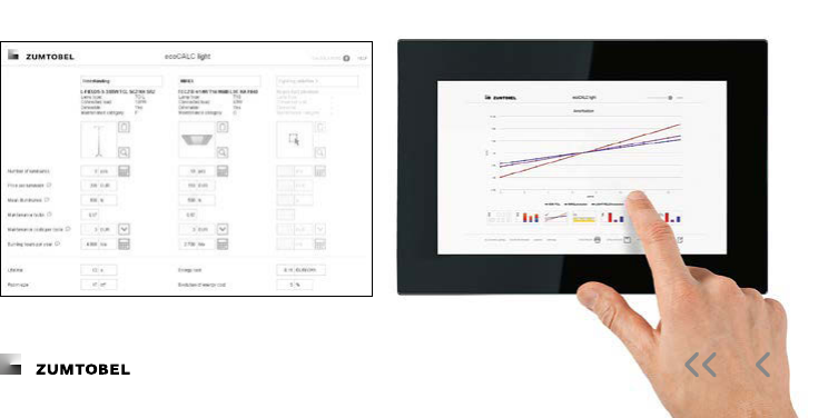
The Lighting Handbook
ecoCALC light
Light enough for the cloud
ecoCALC light can compare up to three sim-
ple lighting solutions online and all necessary
inputs can be made on one page.
Results can be achieved with so few entries
because ecoCALC light works with the
product data from the online catalogue, cal-
culates maintenance intervals automatically
and saves typical settings as default values.
The unique features of ecoCALC are
therefore retained and a luminous intensity
curve can still be output, for example, whilst
maintenance costs are calculated with regard
to the manufacturer’s data for the lamps and
luminaires. A selection of typical existing
luminaires is also provided.
The luminous intensity can also be calcu-
lated directly in ecoCALC light because we
integrate the familiar QuickCalc from the
product pages into the application. This way
it can be ensured that the solutions really are
comparable.
All of the results can then be shown on
a single page and it is of course possible to
enlarge graphics and generate a printout.
But the most important thing is that you
can share your project with colleagues or
customers by simply sending them a link –
no installation is necessary.
ecocalclight.zumtobel.com/app//
Online design tools

The Lighting Handbook
DALEC
Day- and Articial Light with
Energy Calculation
Concept analysis tool for comprehensive
lighting planning
DALEC is a design tool to determine potential
savings for rooms with day and articial
lighting systems. It was developed within the
scope of the K-light research project
“Integrated Day and Articial Light”, which
looked into an integral control approach for
facade systems. The DALEC web application
is the result of a research partnership with
the University of Innsbruck, Bartenbach and
Zumtobel Lighting. DALEC is an easy-to-use
tool for determining energy saving potential
in rooms with daylight and articial light
systems in early project phases. It evaluates
dierent facade and articial light solutions
and determines their inuence on heating
and cooling loads. Quality criteria such as
room temperature or glare control are also
evaluated at the same time.
DALEC has been implemented as an online
service and is available at
dalec.zumtobel.com

The Lighting Handbook
Online product information
Online catalogue
Under the “Download” tab, the online
catalogue provides a list of all product data
available for a specic product.
Available product information:
– Product data sheet incl. maintenance
category
– Photometric data sheets incl. UGR tables
– Photometric data formats Eulumdat, IES
– Drag & drop data for DIALux and Relux
– Brochures
– Installation instructions
Quick access with
URL/article reference:
zumtobel.com/
– CE certicates
– D BIM Revit le
– CAD data: D and D
– Environmental product declaration (EPD)
– Data for automatic circuit breakers
– Label according to EU-VO /

The Lighting Handbook
Mobile online catalogue
Zumtobel’s online product catalogue has
been optimised for access via mobile
devices, enabling users to directly access
information on the complete product range
anywhere and at any time, by means of smart
phones and tablets.
To this end, all you need to do is go to
http://mobile.zumtobel.com (or the page of
the respective country, e.g. http://mobile.
zumtobel.co.uk) via the mobile device’s
browser. As this is not an app, no software
needs to be installed, and access is possible
from various devices.
The system supports iPhones, iPads as
well as Android-based mobile phones and
tablets. Access is, however, also possible
using Blackberry devices OS and higher,
as well as other current smart phones, such
as the Nokia S, for instance.
In the mobile version, too, products can
be accessed directly via a quicklink.
To do so, all you need to do is enter
http://mobile.zumtobel.com followed by
the respective order number
For article number ,
for example, this would be:
http://mobile.zumtobel.com/

The Lighting Handbook
Online product information
QR code
A so-called QR (Quick Response) code is
printed on all cardboard packaging for
Zumtobel luminaires of the standard range.
This code is similar to a bar code and makes
it easy to quickly access information on a
specic product, even when you are not at
the oce.
If you have installed free QR reading
software on your smart phone, all you need
to do is focus your mobile phone’s camera
onto this black-and-white square; you will
then be automatically directed to the
respecti ve product in Zumtobel’s online
catalo gue.
All information available on the product,
such as installation instructions, data sheets
and product details, can be conveniently
retriev ed from the product catalogue. In
order to make it really easy to navigate the
catalogue using a mobile phone as well,
the whole online catalogue has been opti-
mised for mobile devices.

The Lighting Handbook
Any product information required can be
select ed from the online catalogue and
summaris ed in the form of a data sheet.
Additionally, all installation instructions for
the respective product are available in
PDF format. See description of the data sheet
in chapter , page .
For more product information, please refer to:
zumtobel.com/com-en/products
– Complete product information in PDF
format, up to date and country-specic:
gures, charts, images
– Compilation of the product information
select ed in the form of a data sheet
(ZIP le)
– Photometric data sheets
– Data sheets with connecting instructions
for LUXMATE products
– Quick dispatch of any part of the
catalogue by e-mail
Product data sheets and installation instructions

The Lighting Handbook
Online product information
D CAD data: REVIT, ARCHICAD
D CAD data is available in the online cata-
logue. The CAD data can be found in the
download area of the relevant product in
REVIT format – if this is already available for
this product group.
The complete library of data in REVIT and
ARCHICAD format can be retrieved on the
homepage under “SERVICE” as well as
“DOWNLOADS AND SOFTWARE”.
D CAD data: DWG, DXF
D CAD data is available in the online cata-
logue. The CAD data can be found in the
download area for the respective product in
a DWG format.
The complete library of data in an DWG
and DXF format can be retrieved on the
homepage under “SERVICE” as well as
“DOWNLOADS AND SOFTWARE”.
zumtobel.com/com-en/service.htmlrevit
zumtobel.com/com-en/downloads.htmlarchicad
zumtobel.com/com-en/downloads.htmlD-CAD

The Lighting Handbook
The environmental product declaration
(EPD) according to ISO describes the
specic environmental impact of a product.
The declaration is based on the product
catego ry rules (PCR) for “luminaires, lamps
and components for luminaires” set out
accor ding to EN . The life cycle assess-
ment (LCA) was prepared in compliance with
ISO .
The product described serves as a declared
unit. An EPD includes a product description,
data on material composition, manufac-
ture, transport, period of use, disposal and
recycling as well as the results of the life
cycle assessment. It is subjected to independ-
ent testing according to ISO .
EPDs of building products can be compared
only if life cycle assessments have been
calculat ed according to the same PCRs.
This EPD refers to the IBU master EPD for
the Zumtobel Group and can be called up at
bau-umwelt.de/hp/Luminaires-lamps.htm
For more product information, please refer to
zumtobel.com/com-en/products
Environmental product declaration (EPD)

The Lighting Handbook
Map of Light
The Map of Light shows you state-of-the-art
lighting solutions and impressive pictures
of more than projects implemented
all over the world, providing you with
in spiring ideas and new stimuli for forth-
coming projects.
For the Map of Light, please refer to:
zumtobel.com/com-en/lighting_solutions.asp

The Lighting Handbook
Personal notes

The Lighting Handbook
Personal notes

The Lighting Handbook
Personal notes

The Lighting Handbook
Personal notes

The Lighting Handbook
Personal notes

The Lighting Handbook
Personal notes

The Lighting Handbook
Personal notes

The Lighting Handbook
Personal notes

The Lighting Handbook
Personal notes

The Lighting Handbook
Personal notes

The Lighting Handbook
Personal notes
United Kingdom
ZG Lighting (UK) Limited
Chiltern Park
Chiltern Hill, Chalfont St. Peter
Buckinghamshire SL FG
T /()
info.uk@zumtobelgroup.com
zumtobel.co.uk
USA and Canada
Zumtobel Lighting Inc.
Route W
Highland, NY
T //
F //
info.us@zumtobelgroup.com
zumtobel.us
Australia
ZG Lighting Australia Pty. Ltd.
/ Millner Avenue,
Horsley Park, NSW
T
/
info.au@zumtobelgroup.com
zumtobel.com.au
New Zealand
ZG Lighting (NZ) Limited
Jomac Place,
Avondale, Auckland
PO Box , Rosebank,
Auc
kland
T
T /()
F /()
info.nz@zumtobelgroup.com
zumtobel.co.nz
China
Thorn Lighting (Guangzhou) Limited
A Lian Yun Road
Eastern Section,
G
ET
DD, Guangzhou
, P.R. China
T ()
Sales Hotline:
info.cn@zumtobelgroup.com
zumtobel.cn
Hong Kong
ZG Lighting Hong Kong Ltd.
Unit – , /F, Building W,
Phase , Hong Kong Science Park,
New Territories, Hong Kong
T /()
F /()
info.hk@zumtobelgroup.com
Singapore
ZG Lighting Singapore Pte. Ltd.
Kallang Way -/
Singapore
T /
F /
info.sg@zumtobelgroup.com
United Arab Emirates
ZG Gulf LLC
B Street, Al Quoz industrial area ,
P.O.Box: , Dubai,
United Arab Emirates
T
info.ae@zumtobelgroup.com
thornlighting.ae
Qatar
ZG Lighting Trading WLL
Abdul Jaleel Business Centre, Oce
No. , Najma Airport road
P.O.Box:
Doha, Qatar
T
info.qa@zumtobelgroup.com
thornlighting.ae
Romania
Zumtobel Lighting Romania SRL
Radu Greceanu Street, no. ,
Ground Floor, sector
Bucharest
T
F
info.ro@zumtobelgroup.com
zumtobel.com
Hungary
ZG Lighting Hungary Kft.
Váci út
Budapest
T /()
F /()
info.hu@zumtobelgroup.com
zumtobel.hu
Croatia
ZG Lighting d.o.o.
Ulica Petra Hektorovića
Zagreb
T /()
F /()
info.hr@zumtobelgroup.com
Bosnia and Herzegovina
ZG Lighting d.o.o.
Predstavništvo u BiH
Zmaja od Bosne
Sarajevo
T
info.ba@zumtobelgroup.com
Serbia
ZG Lighting d.o.o.
Beton hala – Karađorđeva -
Belgrade
M
info.rs@zumtobelgroup.com
Czech Republic
ZG Lighting Czech Republic s.r.o.
Jankovcova
Praha
Praha
T
F
info.cz@zumtobelgroup.com
zumtobel.cz
Slovak Republic
ZG Lighting Slovakia s.r.o.
Tomášikova
Bratislava
T
info.sk@zumtobelgroup.com
zumtobel.sk
Poland
ZG Lighting Polska Sp. z o.o.
Wołoska a
Platinium Business Park III
- Warszawa
T
info.pl@zumtobelgroup.com
zumtobel.pl
Slovenia
ZG Lighting d.o.o
Štukljeva cesta
Ljubljana
T /()
F /()
info.si@zumtobelgroup.com
zumtobel.si
Russia
ZG Svet JSC
Ocial oce Zumtobel Group
Nizhniy Susalniy pereulok,
/, oce
Moscow
T /()
T /()
info.ru@zumtobelgroup.com
zumtobel.ru
Norway
ZG Lighting Norway AS
Bygdøy allé
Oslo
T
info.no@zumtobelgroup.com
zumtobel.no
Sweden
ZG Lighting Nordic AB
Hyllie Boulevard b
Malmö
T
info.se@zumtobelgroup.com
zumtobel.se
Denmark
ZG Lighting Denmark A/S
Stamholmen , . sal
Hvidovre
T
info.dk@zumtobelgroup.com
zumtobel.dk
Order no. -EN / © Zumtobel Lighting GmbH
Technical data was correct at time of going to press.
We reserve the right to make technical changes without
notice. Please contact your local sales oce for further
information.
Headquarters
Zumtobel Lighting GmbH
Schweizer Strasse
Postfach
Dornbirn, AUSTRIA
T /()/-
info@zumtobel.info
zumtobel.com
ISBN ----
