
1
AT&T U115 Install Guide
Version D6.0.1

2
© 2018 AT&T Intellectual Property. All rights reserved. AT&T, the AT&T logo and all other AT&T marks
contained herein are trademarks of AT&T Intellectual Property and/or AT&T affiliated companies. All
other marks contained herein are the property of their respective owners.
CALIFORNIA PROPOSITION 65 WARNING
WARNING: Cancer and Reproductive Harm – www.P65Warnings.ca.gov

3
רצומב
•
•
• רצומה
• רצומה
• רצומב
• רצומה
•
•
• רצומה
•
•
•
• Class A
ןאוביהלנוישנרטניא ססיורס קרווטנ לבולג יט דנא יט ייא
05107 דול ,הפועתה הדש תיירק ,4 בגנה בוחר
DSA-60PFB-24 1 190250
Class A
4
Table of Contents
Installing the AT&T VPN Gateway U115 ................................................................................................................................................... 5
Step 1: Establish Physical Connectivity to the Internet .............................................................................................................................. 5
Option a. Wired Ethernet Connection ..................................................................................................................................................... 6
Option b. Cellular Connection ................................................................................................................................................................ 6
Step 2: Establish Local Network Connectivity ............................................................................................................................................ 7
Configuring the U115 .................................................................................................................................................................................... 8
Access the U115 Web Interface ................................................................................................................................................................... 8
Primary IPv4 WAN Interface Setup ............................................................................................................................................................ 9
Configuring DHCP ............................................................................................................................................................................... 11
Configuring a Static IP Address............................................................................................................................................................ 12
Configuring PPPoE ............................................................................................................................................................................... 13
Configuring an Always-On Cellular Connection .................................................................................................................................. 14
Configuring a User Controllable Dial as Primary Configuration .......................................................................................................... 16
Cellular service verification .................................................................................................................................................................. 18
Administrator Access................................................................................................................................................................................. 19
Establishing VPN Connectivity ................................................................................................................................................................. 20
LAN Port Configuration ............................................................................................................................................................................. 22
VLANS ....................................................................................................................................................................................................... 22
Hub Mode .................................................................................................................................................................................................. 25

5
Installing the AT&T VPN Gateway U115
Unpack the AT&T VPN Gateway U115 (“U115”), the cables, antennas, and the power supply. Connect the antennas and
power supply. Make sure the power switch is in the on position.
Note: In certain regions, antenna’s and the cellular modem are not included.
Installation steps vary depending on type of Internet connection and type of local network connectivity. See Figure 1 for
connectors on the rear panel of the U115.
Figure 1: U115 Rear Panel
Follow the guide below to determine the necessary setup steps for your environment.
Step 1: Establish Physical Connectivity to the Internet
In many cases, a wired Ethernet connection will be provided by your ISP. This type of connection includes DSL, Cable
and Managed Internet Connections. It is also possible to connect to the Internet via high speed cellular access, in which
case you should proceed to the appropriate section in this guide.
Once an Internet Connection has been established, the U115 will try to retrieve its configuration from the network, and if
successful, may perform an automatic reboot to pick up the new configuration. This should occur within the first 2-3
minutes after initial power on. Wait for a steady GREEN ONLINE light on the front panel to indicate the U115 is ready for
use.
Basic connectivity is shown in Figure 2. Devices in the local network are connected to one or more of the LAN ports on
the back of the U115; the broadband connection is usually established via the WAN1 port.

6
Figure 2: Basic Network Connectivity
Option a. Wired Ethernet Connection
Use a straight-through Ethernet cable (usually provided by your Broadband Internet Service Provider) to connect your
Internet broadband interface device to the Ethernet port labeled WAN1 on the U115. The U115 should be connected
directly to the broadband interface device.
Dynamic Host Control Protocol (DHCP) is the default configuration for Internet IP addressing of the U115 Internet network
interface. If your device automatically obtains an address from your ISP through DHCP, it should auto-configure shortly
after powering up.
If your Broadband Internet Service Provider supplied you with a static IP address or PPPoE account information for use
with your broadband connection, you will need to perform additional configuration of the primary interface through the
U115 web interface in order to establish Internet access and to retrieve device configuration. See “Configuring a Static
IP Address” or “Configuring PPPoE” later in the guide.
Option b. Cellular Connection
Certain U115's will have an imbedded cell card and SIM already installed. If the device has an imbedded call card and
SIM, please work with your AT&T account team to activate the SIM.
If the device will connect via an approved cellular USB modem, then insert the modem into one of the two USB ports on
the back of the U115.
The U115 needs basic setup of the cellular modem via the web interface before it can connect to the Internet to retrieve its
configuration. See “Configuring an Always-On Cellular Connection” or “Configuring a User Controllable Dial as
Primary Configuration” later in the guide. After a cellular connection is set up and connected the GREEN ONLINE light
on the front panel will blink to indicate the U115 is using a cellular connection.

7
Step 2: Establish Local Network Connectivity
In most cases, your devices will attach directly to the U115 via one of the 8 LAN ports with an Ethernet cable. The Local
LAN ports are auto-sensing, so either a straight-through or a crossover cable can be used interchangeably.
The default configuration for computers attaching to any of the U115 Local LAN ports is DHCP. If you are not sure if you
are using DHCP for your LAN IP addressing, please contact your Information Services (IS) Department for assistance
before proceeding.
If your computer is configured to use DHCP, but the U115 is not providing your computer with an IP address, please
contact your IS Department. In this case you will not be able to access the web Interface as described below.
Note: After the AT&T has retrieved its configuration, the IP addresses given out on the LAN ports are likely to change
from the default values the device was configured for. If the IP addressing does change, it may be necessary to reboot or
reconfigure your devices attached to the U115 in order to obtain/assign a valid IP address to use when accessing the
Local LAN ports of the U115.

8
Configuring the U115
In most cases, no user-level configuration is required as an IP address is retrieved automatically through DHCP and the
device configuration is retrieved from the network. In some cases, it is necessary to perform some initial configuration
through the web Interface – for example if the primary Internet connection needs to be manually configured prior to use.
Access the U115 Web Interface
The U115 web interface can be accessed from a computer attached to a LAN port. The web interface can be used to
access various administration functions and can allow the VPN connection to be controlled.
1. Open your web browser.
2. In the Address or Location box enter http://attvpngateway.att.com and press the Enter key.
3. This will take you to one of several possible initial pages, depending on your configuration and connectivity
options. Common navigation icons appear on the upper left side of each page for access to “Home”, “Control
Panel” and “Help”
If the U115 has already retrieved its configuration, it may have been configured for Administrator access. See
Administrator Access on page 19 for more information on gaining administrator access to the web interface.

9
Primary IPv4 WAN Interface Setup
To configure the primary interface for something other than DHCP (or to change DHCP settings), follow these steps:
1. Access the web interface as described on page 8.
2. Click on the Control Panel navigation icon.
3. Click the entry for Network Settings to display the Network Settings sub-menu and click the entry for WAN IPv4
Settings as shown in Figure 3.
Figure 3: Network Settings Selection

10
Figure 4 will be displayed where you will be given the opportunity to select your primary connection type.
Figure 4: IPv4 Settings Window
If you are not sure how your Internet Access should be configured, contact your IS department. Two basic types of
connection are offered. An “Always-On Internet Connection” means that the connection will normally always be available,
and the U115 will try to re-establish connectivity if the connection is lost. The other type is for where an Internet
connection is only established when required. This is commonly used where having a connection up always may be
expensive and there are periods of time when the connection is not required. Continue configuration from the section
appropriate to your connection type.

11
Configuring DHCP
To configure DHCP, follow these steps after reaching Figure 4:
1. Select the radio button next to “DHCP” on Figure 4 and click OK to proceed to the DHCP set up window.
2. Select the DHCP options required by your ISP on Figure 5. Most ISPs do NOT require any of these values to be
set.
3. Press OK to save the new settings.
4. At the end of the setup, you will be asked to reboot to pick up the new configuration. After reboot, skip to the
section titled “Establishing VPN Connectivity” on page 20.
Figure 5: DHCP Settings

12
Configuring a Static IP Address
To configure a static IP address, follow these steps after reaching Figure 4:
1. Select the radio button next to “Static” on Figure 4 and click OK to proceed to the Static IP set up window.
2. Enter the Static IP information requested on Figure 6 and press OK to save the new settings. The Static IP
information is provided by your ISP.
3. At the end of the setup, you will be asked to reboot to pick up the new configuration. After reboot, skip to the
section titled “Establishing VPN Connectivity” on page 20.
Figure 6: Static IP Settings

13
Configuring PPPoE
To configure PPPoE Account information, follow these steps after reaching Figure 4:
1. Select the radio button next to “PPPoE” on Figure 4 on and click OK to proceed to the to the PPPoE set up
window.
2. Enter the information requested on Figure 7 and press OK to save the new settings.
3. At the end of the setup, you will be asked to reboot to pick up the new configuration. After reboot, skip to the
section titled “Establishing VPN Connectivity” on page 20.
Figure 7: PPPoE Settings

14
Configuring an Always-On Cellular Connection
To configure an Always-On Cellular connection, follow these steps after reaching Figure 4:
1. Ensure your supported Cellular modem is inserted into one of the two USB ports on the back of the U115 or if an
internal modem is installed, that a SIM has been inserted.
2. Select the radio button next to Cellular in the “Always-On” section and click OK to proceed to the setup
sequence.
3. Select your modem type from the drop-down menu on Figure 8. For more detailed information on supported
Cellular modems and associated configuration, please contact your IS Department.
4. The Access Point Name and AT Strings are optional fields that you can enter information into if they are required.
If these fields are not required, then leave them blank. Click NEXT to proceed to the next page.
5. Enter the phone number provided by your Cellular service provider on Figure 9.
6. Enter the user ID and password provided by your Cellular service provider. Some networks/APNs don't use the
user ID and some Cellular service providers require that the user ID is NOT sent. In those cases, enter “empty”
(without quotes) for both the user ID and password to ensure that no user ID and password information is sent in
the authentication flow.
7. At the end of the setup, you will see a summary of the configuration and will be asked to reboot to pick up the
new configuration. After reboot, skip to the section “Establishing VPN Connectivity” on page 20.

15
Figure 8: Cellular Always On Settings- Modem Properties
Figure 9: Cellular Always On Settings - Login Information

16
Configuring a User Controllable Dial as Primary Configuration
To configure a Cellular User Controllable Dial as Primary connection, follow these steps after reaching Figure 4:
1. Ensure your supported Cellular USB modem is inserted into one of the two USB ports on the back of the U115 or
if an internal modem is installed that a SIM has been inserted.
2. Select the radio button next to “Cellular” in the “User Controllable Dial as Primary Connection” section and click
OK to proceed to the setup sequence.
3. Select your modem type from the drop down menu on Figure 10. For more detailed information on supported
Cellular modems and associated configuration, please contact your IS Department.
4. The Access Point Name and AT Strings are optional fields that you can enter information into if they are required.
If these fields are not required, then leave them blank. Click NEXT to proceed to the next page.
5. Enter the phone number provided by your Cellular service provider on Figure 11.
6. Enter the user ID and password provided by your Cellular service provider. Some networks/APNs don't use the
user ID and some Cellular service providers require that the user ID is NOT sent. In those cases, enter “empty”
(without quotes) for both the user ID and password to ensure that no user ID and password information is sent in
the authentication flow.
7. Select your Dial Internet connection method from the drop-down menu.
8. At the end of the setup, you will see a summary of the configuration and will be asked to reboot to pick up the
new configuration. After reboot, skip to the section titled “Establishing VPN Connectivity” on page 20.

17
Figure 10: Cellular Dial as Primary Settings - Modem Properties
Figure 11: Cellular Dial as Primary Settings - Login Information

18
Cellular service verification
After completing the setup of either mode of the cellular connection, it is important to determine that there is adequate
signal strength before deciding on a final installed position. Cellular coverage can vary, even over a short distance, and a
bad placement of the AT&T U115 can result in substandard or even non-existent cellular service.
If the device is using an imbedded Cellular modem, the signal strength will be displayed on the front panel, right side. The
color of the light labeled "CELL" will indicate the network connectivity as follows:
• Blue - LTE
• Green - non-LTE 4G / 3G (UMTS)
If the device is using an external USB modem, you can check the signal strength by pressing the “RESET” button on the
back while powered on with the Cellular USB modem inserted. A paper clip or other sharp object will be required to
properly depress this button.
The signal strength will be represented by a sequence of LEDs illuminated on the front panel. Up to six LEDs, starting with
the “online” light may be illuminated depending on detected strength. The signal strength will appear in this form for five
seconds. At least three LEDs of signal strength are recommended.
Figure 12: Cellular Signal Strength Display
The unit should be installed in a location that gives optimal signal strength.
Note: After the final location has been determined by the best signal strength the U115 needs to be rebooted in order to
re-establish the cellular connection.

19
Administrator Access
One or more users may be designated as administrators by your IS Department. If your U115 was set up for administrator
access, Figure 13 is displayed and you must select your access level. You must be a designated administrator to
configure or control the U115. Select Administrator, enter the password provided by your IS Department, and click OK.
Selecting General User and then clicking OK restricts the current session to be view only. Certain functionality, such as
the ability to terminate the VPN connection, is disabled.
If an Administrator password is not required Figure 13 is not displayed. The U115 must be able to retrieve configuration
from the network in order to implement Administrator access.
Figure 13: Administration Panel

20
Establishing VPN Connectivity
The authentication mode of your U115 is determined by the service parameters ordered by your IS Department. All
configurations require a username and password of some form and may also require other information. This information
may be downloaded from the network and the U115 may be set to automatically establish connectivity. To establish a
VPN connection with your U115 follow these steps:
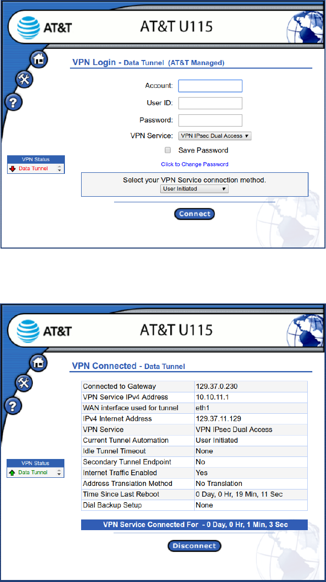
1. Open your web browser as described under “Access the U115 Web Interface” on page 8 and if necessary click
the Home button to view the Login page. The form of the page will depend on the network and type of
authentication configured. Figure 14 shows a Login page for an AT&T Managed connection where the VPN
Service connection method and Dial Backup VPN Service connection method are configurable by the user.
2. One or more VPN connections may have been defined. Each VPN connection will be represented in a status box
on the left side of the page, showing the current state of each connection. If there is more than one VPN
connection defined, only the first VPN connection can be user controlled. The others will be established and
maintained automatically. The user controllable connection status will always be the top entry in the status box.
3. If user input is required to establish the primary VPN connection, provide the requested information and click
Connect.
4. The U115 authenticates your credentials and establishes a secure VPN connection to your network.
5. A status page will be shown like Figure 15 until the VPN connection is terminated.
21
Figure 14: Example of Login Page for AT&T Managed
Figure 15: Example of Connected Page

22
LAN Port Configuration
VLANS
VLAN support allows segmentation of the 8 Local LAN ports into different logical LANs, each with its own address range,
and addressing method (DHCP, DHCP Relay, or static). If your U115 has been configured for VLANs, as part of
installation you will need to know which of the 8 Local LAN Ports attach to each network.
You can view the VLAN configuration through the U115 web interface as described below.
After initial power on, and once the Internet Connection has been correctly configured, the U115 will retrieve its
configuration from the network and will likely perform an automatic reboot to pick up the new configuration. This should
occur within the first 2-3 minutes after initial power on. You will not be able to view the VLAN configuration until the
U115 has successfully retrieved its configuration.
1. Following the automatic reboot open your web browser as described in “Access the U115 Web Interface” on
page 8. It may be necessary to reboot or reconfigure your devices attached to the U115 in order to obtain/assign
a valid IP address if the IP addressing was changed when the U115 retrieved its VLAN configuration.
2. Click on the Control Panel navigation icon.
3. Click the entry for Network Settings to display the Network Settings sub-menu and click the entry for Local LAN
Settings as shown in Figure 16.
4. The next window will display the Local LAN Settings. If VLANs have been configured, the display will appear as
in Figure 17. If VLANs have not been configured, the display will appear as in Figure 19. If no VLANs have
been configured, skip to the description for “Hub Mode” on page 25.
5. The display shows several rows, sorted by VLAN ID that describes which back-panel Ethernet ports are assigned
to each VLAN. The numbers in the Port column correspond to the numbers printed on the back of the U115.
6. Attach your Local LAN cables to an appropriate port based on designated VLAN. If more than one port has been
allocated to a VLAN, any of those ports can be used.
7. If you are not sure of the Network-to-VLAN number mapping, click on any of the VLAN ID hyperlinks to view
detailed information on the VLAN.
8. The next window will display the details for the VLAN. The format and content depend on factors such as
whether DHCP or DHCP relay are being used, or whether static IP addresses have been configured. In the
example for Figure 18, DHCP is configured and so the range of IP addresses and subnet mask is displayed.
Information on any addresses already given out using DHCP will also appear on this window.
9. If you are still unsure what VLAN IDs and ports apply to your local networks, contact your IS Department.
10. When complete, return to “Establishing VPN Connectivity” on page 20.

23
Figure 16: Navigation to Local LAN Settings
Figure 17: Local LAN Settings – VLANS

24
Figure 18: VLAN DHCP Configuration

25
Hub Mode
If no VLANs have been configured by your IS Department all eight Local LAN ports on the back of the U115 are
considered equivalent. The Local LAN Settings page will result in the basic port information display as shown in Figure
19. In this case, Local LAN equipment can be plugged into any available port on the back of the U115. If you see this
page and you think that VLANs SHOULD have been configured, please contact your IS department.
When complete, return to “Establishing VPN Connectivity on page 20.
Figure 19: Local LAN Settings - Ports
Version D6.0.1
© 2018 AT&T Inc. All Rights Reserved.
